
Welcome back! In Part 1 we configured and prepared NSX to participate in a BGP EVPN control and data plane. In this part we continue with configuration of the VyOS router. Once both NSX and VyOS are configured we’ll verify that everything is working as intended.
Lab Overview
The lab environment for this exercise consists of the following components:
- vCenter 8.0 Update 1c
- ESXi 8.0 Update 1c
- NSX Manager 4.1.0.2
- 2 x NSX Edge nodes (VM form factor, Large)
- 1 x Tier-0 Gateway
- 1 x VyOS 1.4 router (VM)
The following table lists the configuration items that are relevant for this article.
| Item | Value | Description | Scope/Span | Configured |
| VLAN 244 | 10.203.244.0/24 | VLAN for Geneve transport | Edge nodes, ESXi hosts | Yes |
| VLAN 246 | 10.203.246.0/24 | VLAN for BGP Uplink 1 | Edge nodes | Yes |
| VLAN 247 | 10.203.247.0/24 | VLAN for BGP Uplink 2 | Edge nodes | Yes |
| VLAN 10 | 172.16.10.0/24 | Tenant Red VLAN | VyOS, VRF Red | No |
| VLAN 20 | 172.16.20.0/24 | Tenant Blue VLAN | VyOS, VRF Blue | No |
| Segment Red | 10.204.245.0/24 | Tenant Red NSX overlay segment | NSX, VRF Red | No |
| Segment Blue | 10.204.246.0/24 | Tenant Blue NSX overlay segment | NSX, VRF Blue | No |
| dummy/loopback | 192.168.100.0/24 | IP CIDR for VXLAN TEPs | VyOS, Edge nodes | n/a |
| VyOS router ASN | 65240 | BGP ASN on the VyOS router | VyOS | Yes |
| NSX Tier-0 ASN | 65241 | BGP ASN on the NSX Tier-0 gateway | NSX | Yes |
| RD VRF Red NSX | 65241:1 | Route Distinguisher for Red VRF in NSX | NSX | No |
| RD VRF Blue NSX | 65241:2 | Route Distinguisher for Blue VRF in NSX | NSX | No |
| VNI Pool | 75001 – 75010 | EVPN/VXLAN VNI Pool | NSX | No |
| VNI Red | 75001 | VNI for Red VRF | NSX | No |
| VNI Blue | 75002 | VNI for Blue VRF | NSX | No |
Diagram
Below the high-level diagram showing what it is we’re about to build.
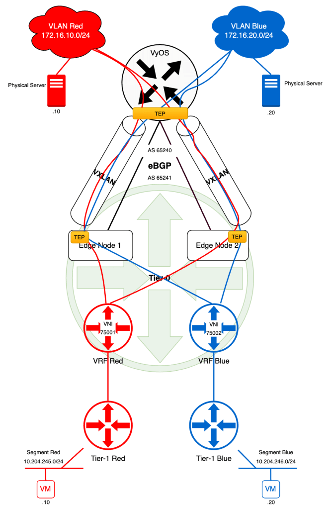
We’re in the process of creating isolated network data paths for our tenants “Red” and “Blue”. By the end of this exercise each tenant’s VM will be able to communicate with that tenant’s physical server. The VMs are connected to NSX overlay segments and the physical servers to isolated VLANs.
Preparing the VyOS Router
Like NSX, the VyOS router needs to be configured for BGP EVPN. There are quite some steps involved so we better get started!
Step 1 – Configure BGP Settings
eBGP is up and running between the NSX Tier-0 gateway and the VyOS router but we need to configure some additional settings in order to make the router ready for participation in BPG EVPN.
Advertise L2VPN EVPN Capability
VyOS needs to inform its NSX BGP neighbors that it’s capable of doing L2VPN EVPN. So for each neighbor entry we need to add the following configuration:
set protocols bgp neighbor 10.203.246.2 address-family l2vpn-evpn
set protocols bgp neighbor 10.203.246.3 address-family l2vpn-evpn
set protocols bgp neighbor 10.203.247.2 address-family l2vpn-evpn
set protocols bgp neighbor 10.203.247.3 address-family l2vpn-evpn
Advertise VXLAN VNIs
VXLAN VNIs need to be advertised back and forward between NSX and VyOS and the following command accomplishes this on the VyOS router:
set protocols bgp address-family l2vpn-evpn advertise
Step 2 – Create Dummy Interfaces
For the router-internal transport of the VXLAN encapsulated traffic we need to “front” the VXLAN interfaces (created in the next step) with a a dummy interface. VyOS dummy interfaces are basically loopback interfaces:
set interfaces dummy dum0 address 192.168.100.100/32
The IP adress here is taken from the “dummy/loopback CIDR” item in the table above. As you might remember we used “192.168.100.102” and “192.168.100.103” as EVPN Tunnel Endpoints on the NSX Tier-0 gateway.
These IP addresses can be anything really as long as they don’t overlap with something existing of course. The important thing is that they’re being advertised to the EVPN counterpart.
Advertise dum0 Interface IP Address Through eBGP
One way to accomplish is by simply adding the IP address of the dum0 interface to the existing eBGP dynamic routing process that’s already running between the NSX Tier-0 gateway and the VyOS router:
set protocols bgp address-family ipv4-unicast network 192.168.100.100/32
Step 3 – Validate
Now is a good time to verify that our Tier-0 gateway understands that the VyOS router is capable of doing L2VPN EVPN and that dum0’s IP address is in the route table.
The easiest way to do this is by logging into an NSX edge node through SSH and use the NSXCLI.
First we check in which VRF our Tier-0 SR is living:
get gateway
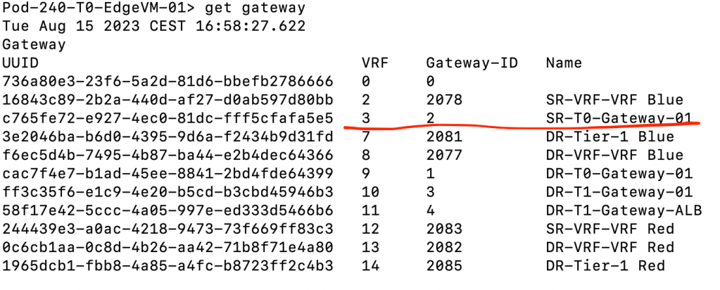
The Tier-0 SR is in VRF #3 so lets enter that context:
vrf 3
Now we can check what it knows about its neighbor the VyOS router:
get bgp neighbor
And we’re interested in the capabilities that are being advertised by the neighbor:
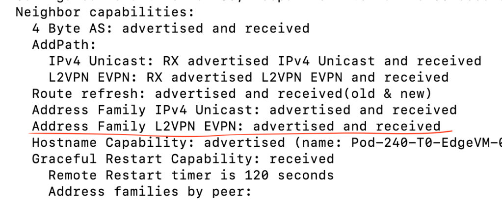
“Address Family L2VPN EVPN: Advertised and received” looks good to me. Next we inspect the route table within the same VRF (Tier-0 SR):
get route bgp

“192.168.100.100/32” ended up in the route table. Twice because we are double peered with the VyOS router over two VLANs so that’s what we expected. Thumbs up!
Step 4 – Create VXLAN Interfaces
The VyOS VXLAN interfaces are responsible for encapsulation and decapsulation of L2 frames. These are essentially the TEPs on the VyOS side. We create one VXLAN interface per tenant:
Tenant Red:
set interfaces vxlan vxlan75001 vni 75001
set interfaces vxlan vxlan75001 port 4789
set interfaces vxlan vxlan75001 mtu 1600
set interfaces vxlan vxlan75001 parameters nolearning
set interfaces vxlan vxlan75001 source-address 192.168.100.100
Tenant Blue:
set interfaces vxlan vxlan75002 vni 75002
set interfaces vxlan vxlan75002 port 4789
set interfaces vxlan vxlan75002 mtu 1600
set interfaces vxlan vxlan75002 parameters nolearning
set interfaces vxlan vxlan75002 source-address 192.168.100.100
Step 5 – Create VRFs
Each tenant will have its own VRF within the VyOS router as well. The VRFs contain the tenant-specific settings for BGP and EVPN like route distinguisher, route-targets as well as VNI.
Tenant Red:
set vrf name red protocols bgp address-family ipv4-unicast redistribute connected
set vrf name red protocols bgp address-family l2vpn-evpn advertise ipv4 unicast
set vrf name red protocols bgp address-family l2vpn-evpn rd 65240:1
set vrf name red protocols bgp address-family l2vpn-evpn route-target import 65241:1
set vrf name red protocols bgp address-family l2vpn-evpn route-target export 65240:1
set vrf name red table 1002
set vrf name red vni 75001
Tenant Blue:
set vrf name blue protocols bgp address-family ipv4-unicast redistribute connected
set vrf name blue protocols bgp address-family l2vpn-evpn advertise ipv4 unicast
set vrf name blue protocols bgp address-family l2vpn-evpn rd 65240:2
set vrf name blue protocols bgp address-family l2vpn-evpn route-target import 65241:2
set vrf name blue protocols bgp address-family l2vpn-evpn route-target export 65240:2
set vrf name blue vni 75002
Step 6 – Create VIFs
Following our diagram, each tenant should receive its own VLAN in the data center where the tenant’s physical server is to be connected. Let’s instantiate the VIFs for these:
set interfaces ethernet eth1 vif 10 description "Tenant Red VLAN"
set interfaces ethernet eth1 vif 20 description "Tenant Blue VLAN"
Note that we do not assign IP addresses to the VIF interfaces. Not directly at least (hint: check Step 7).
FYI. My VyOS router has two physical interfaces: eth0 and eth1. The eth0 interface is used as uplink to an upstream router and eth1 is an 802.1q trunk on which the different VIFs reside. So therefore the tenant VIFs are backed by eth1 and become sub-interfaces of eth1.
Step 7 – Create Bridge Interfaces
So far, all the configuration has been around logical constructs. At some point we need to “hit the road” and that point is here and now.
In VyOS, in the case of VXLAN, we bring logical and physical together in a bridge interface. We create one bridge interface per tenant.
Tenant Red:
set interfaces bridge br75001 vrf red
set interfaces bridge br75001 address 172.16.10.1/24
set interfaces bridge br75001 member interface vxlan75001
set interfaces bridge br75001 member interface eth1.10
Tenant Blue:
set interfaces bridge br75002 vrf blue
set interfaces bridge br75002 address 172.16.20.1/24
set interfaces bridge br75002 member interface vxlan75002
set interfaces bridge br75002 member interface eth1.20
Through the bridge interface we, indirectly, assign an IP address to the tenant VIFs (eth1.10 and eth1.20) which are member interfaces of the bridge interfaces.
This completes the configuration of the VyOS router. Quite a few steps and explaining every line would take a lot of space but I hope most of it is rather self explanatory.
For your reference I have published my VyOS config for this lab on GitHub in case you want to compare or see the big picture (or find mistakes and want to suggest improvements).
Validation
NSX configured and VyOS configured. It’s about time to verify that we have a working BGP EVPN control and data plane.
The VyOS Side
On the VyOS side of things we use a couple of commands to check the control plane status:
show bgp l2vpn evpn
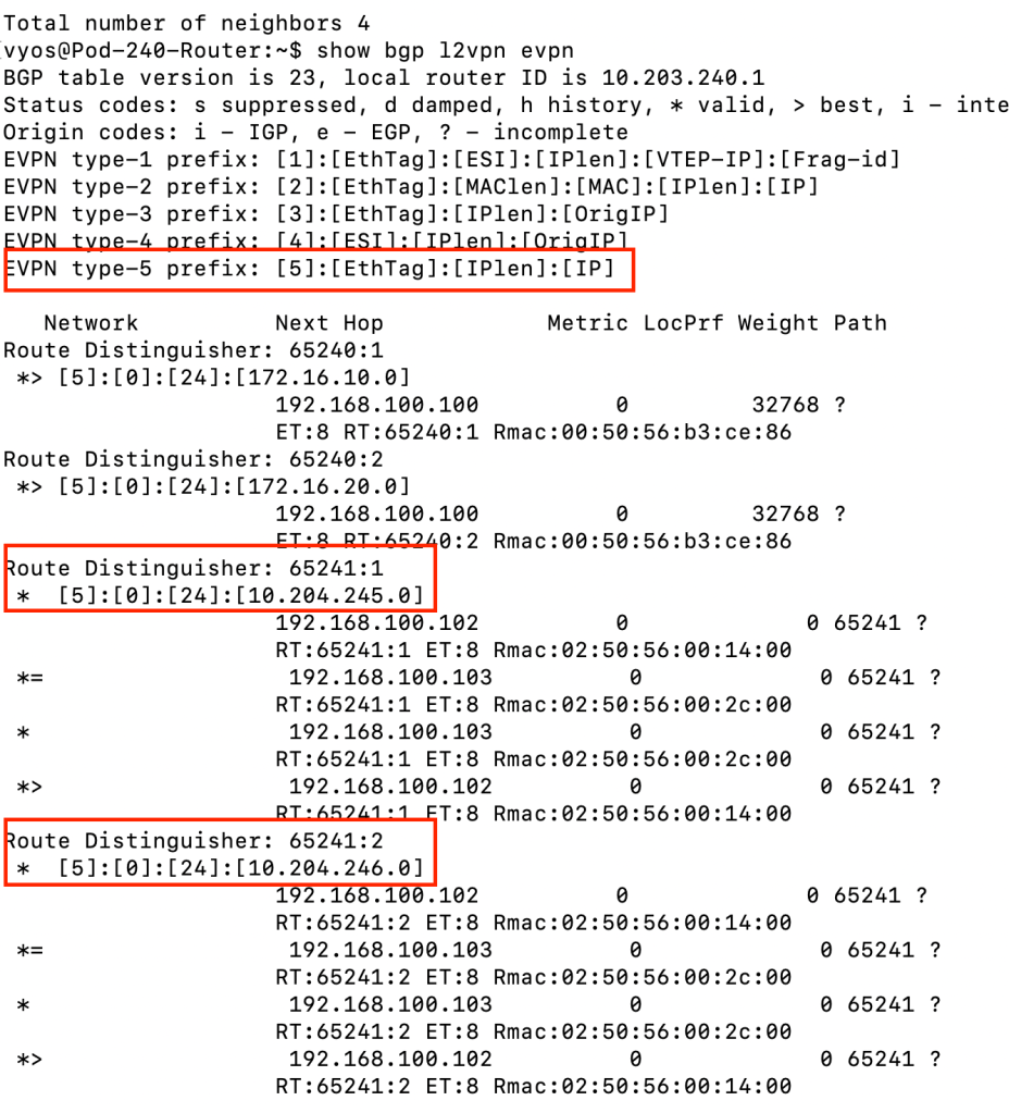
As we can see in the screenshot above, EVPN type-5 prefixes for 10.204.245.0/24 and 10.204.246.0/24 (tenant Red’s and tenant Blue’s NSX overlay segment IP subnets) have been received through BGP EVPN. Both VXLAN TEPs on the Tier-0 gateway (192.168.100.102 and 192.168.100.103) have sent the prefixes.
show ip route vrf red
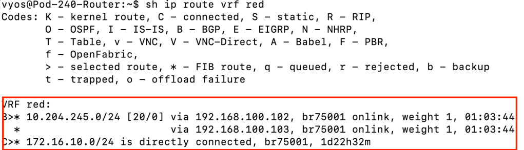
The above command and screenshot show us the route table for VRF Red. We can see that it contains a route to tenant Red’s NSX overlay IP subnet. Learned through BGP and distributed by the Tier-0 VXLAN TEPs.
By now it’s pretty clear that we have a working BGP EVPN control plane. To test the functioning of the data plane on the VyOS router side we can run a simple ping from VRF Blue to tenant Blue’s virtual machine connected to tenant Blue’s NSX overlay segment:
ping 10.204.246.20 vrf blue count 4
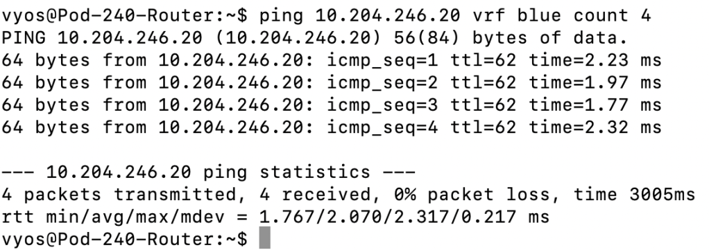
We have a a functional data plane! Can we ping tenant Red’s virtual machine from VRF Blue?
ping 10.204.245.10 vrf blue count 4

Nope, there is no route i VRF Blue’s route table that leads to the 10.204.245.0/24 network.
The NSX Side
We have strong indications that our BGP EVPN configuration is working, but let’s also have a look at how to verify things from the NSX side.
Beginning on one of the NSX edge nodes we enter the VRF for “SR-VRF-VRF Red” and inspect the route table:
get route bgp
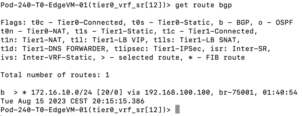
We can see that the IP subnet assigned to tenant Red’s VLAN (172.16.10.0/24) ended up in VRF Red’s route table in NSX.
Just like on the VyOS side we can check the status for EVPN from the edge node. This is done from the Tier-0 SR VRF:
get bgp evpn
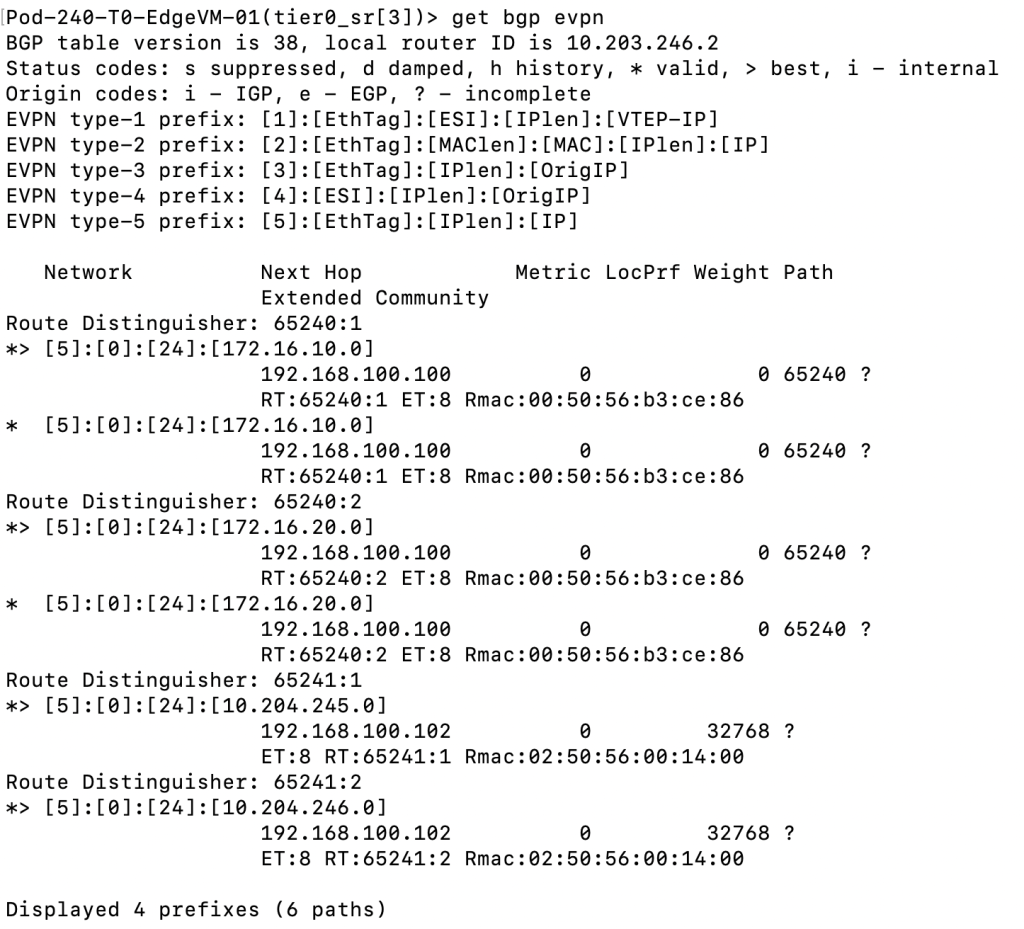
The output is very similar to what we saw when running the “show bgp l2vpn evpn” on the VyOS router. Type-5 EVPN prefixes are being received.
The Workload Side
Now that we’ve validated functionality on the router level, it’s perhaps a good time to move up a couple of layers and make sure that workloads also can leverage this brand new and shiny network data path.
In the screenshot below we’ve logged in to tenant Red’s VM:
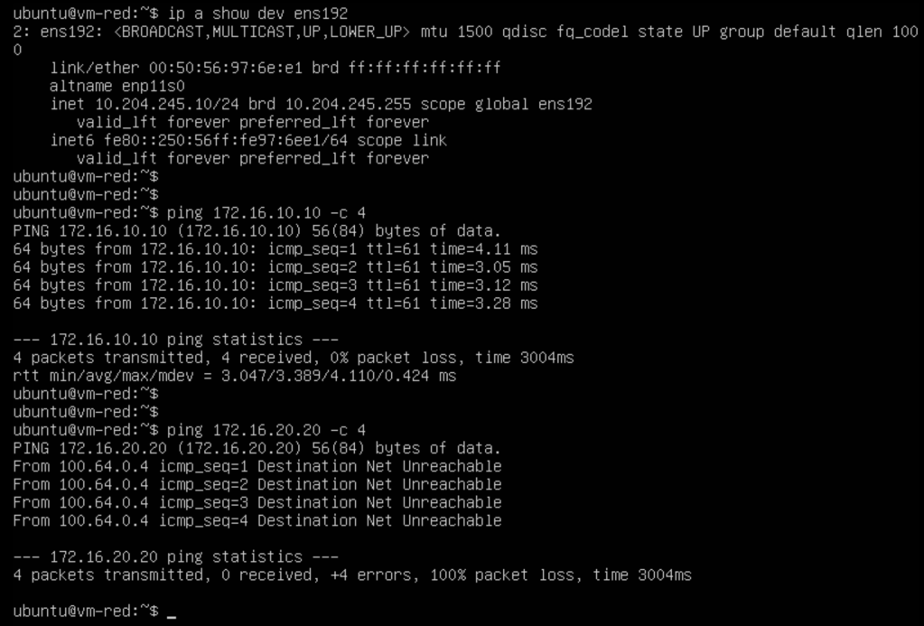
After verifying the VM’s IP address (10.204.245.10/24) we run a ping to the tenant’s physical server (172.16.10.10/24) connected to the tenant’s VLAN which is successful. We also try to ping tenant Blue’s physical server (172.16.20.20/24) which is not successful as expected.
In the screenshot below we’ve logged in to tenant Blue’s physical server:
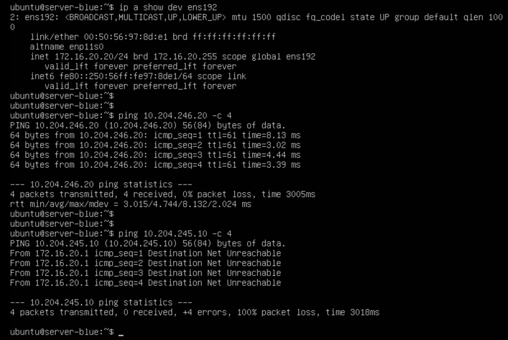
After verifying the VM’s IP address (172.16.20.20/24) we run a ping to the tenant’s virtual machine (10.204.246.20/24) that is connected to the tenant’s NSX overlay segment which is successful. We also try to ping tenant Red’s virtual machine (10.204.245.10) which is not successful as expected.
The tenant workloads can use their respective data path. Isolated from NIC to NIC, traversing NSX overlay into an isolated VLAN. inthe data center. Mission accomplished
Summary
It does not get more exciting than this I’m afraid. Or maybe it’s exciting enough. 🙂
Anyhow, in this second and last part we configured the VyOS router to play BGP EVPN ball with NSX. Configuring the VyOS side was a bit more work compared to the NSX side, but by no means difficult. Once configuration on both sides was in place we verified that we had a functional EVPN control and data plane using VyOS and NSX CLI commands as well as ping tests directly from the involved tenant workloads.
In these articles we looked specifically at VyOS because that’s what I have my lab, but you probably understand that this technology will most likely work with the physical network equipment you have in your data center today.
Don’t hesitate to reach out if you have any questions. Thanks for reading.

Leave a comment