
Recently I’ve been looking into setting up BGP EVPN between VMware NSX and VyOS router. I’m using VyOS quite a lot in labs and demos, often as the counterpart to a Tier-0 gateway, and wanted to find out if it was capable of a somewhat more advanced feature like BGP EVPN.
It took some research as well as some good ol’ trial and error, but I’m happy to report that I was successful in my endeavor. And to be honest, it is a pretty straight forward process, but things usually are once you know how to do it. 🙂
Sharing is caring and that’s why in this and the next article I will walk through setting up BGP EVPN between NSX and VyOS. In part 1 we will deal with configuring and preparing the NSX environment and in part 2 we’ll configure the VyOS router and make sure everything comes together.
Before we begin let’s have a quick look at some background around what BGP EVPN is and how it’s used in data centers and within NSX.
BGP EVPN
Ethernet VPN (EVPN) is a BGP distributed control plane for Network Virtualization Overlay (NVO). It provides Layer 2 and Layer 3 connectivity over underlay networks. Initially it was designed for use with MPLS in service provider networks but EVPN has been widely adopted in data centers as a control plane mechanism for VXLAN overlay networking due to advantages in BGP scalability and flexibility.
The use case for BGP EVPN In NSX
Within NSX, BGP EVPN technology is used to interconnect and extend NSX-managed overlay networks to other data center environments that are not managed by NSX. VXLAN encapsulation is used between NSX TEPs (edge nodes and hypervisors) and external network devices to ensure data plane compatibility.
In NSX you can choose between two connectivity modes for the EVPN implementation: Inline mode and Route Server mode.
Inline mode
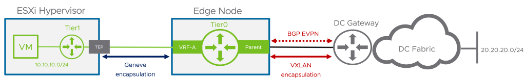
In this mode the Tier-0 Gateway joins the BGP EVPN control plane together with external routers to exchange routing information. The data plane consists of NSX edge nodes which forward traffic to and from the hypervisors. TEPs used for the data plane VXLAN encapsulation are configured on each edge node.
Route Server mode
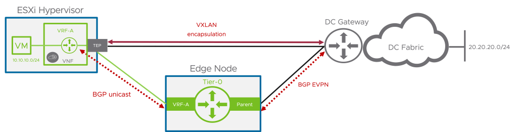
As with inline mode the Tier-0 Gateway establishes a BGP EVPN control plane to exchange routing information with the external routers but in the data plane it is the ESXi hypervisor that forwards the traffic. The same TEPs that are used for the GENEVE encapsulation (east-west traffic) are used for the BGP EVPN data plane VXLAN encapsulation.
In these articles we will focus on configuring BGP EVPN in Inline mode.
Lab Overview
The lab environment for this exercise consists of the following components:
- vCenter 8.0 Update 1c
- ESXi 8.0 Update 1c
- NSX Manager 4.1.0.2
- 2 x NSX Edge nodes (VM form factor, Large)
- 1 x Tier-0 Gateway
- 1 x VyOS 1.4 router (VM)
The following table lists configuration items that are relevant for this article.
| Item | Value | Description | Scope/Span | Configured |
| VLAN 244 | 10.203.244.0/24 | VLAN for Geneve transport | Edge nodes, ESXi hosts | Yes |
| VLAN 246 | 10.203.246.0/24 | VLAN for BGP Uplink 1 | Edge nodes | Yes |
| VLAN 247 | 10.203.247.0/24 | VLAN for BGP Uplink 2 | Edge nodes | Yes |
| VLAN 10 | 172.16.10.0/24 | Tenant Red VLAN | VyOS, VRF Red | No |
| VLAN 20 | 172.16.20.0/24 | Tenant Blue VLAN | VyOS, VRF Blue | No |
| Segment Red | 10.204.245.0/24 | Tenant Red NSX overlay segment | NSX, VRF Red | No |
| Segment Blue | 10.204.246.0/24 | Tenant Blue NSX overlay segment | NSX, VRF Blue | No |
| dummy/loopback | 192.168.100.0/24 | IP CIDR for VXLAN TEPs | VyOS, Edge nodes | n/a |
| VyOS router ASN | 65240 | BGP ASN on the VyOS router | VyOS | Yes |
| NSX Tier-0 ASN | 65241 | BGP ASN on the NSX Tier-0 gateway | NSX | Yes |
| RD VRF Red NSX | 65241:1 | Route Distinguisher for Red VRF in NSX | NSX | No |
| RD VRF Blue NSX | 65241:2 | Route Distinguisher for Blue VRF in NSX | NSX | No |
| VNI Pool | 75001 – 75010 | EVPN/VXLAN VNI Pool | NSX | No |
| VNI Red | 75001 | VNI for Red VRF | NSX | No |
| VNI Blue | 75002 | VNI for Blue VRF | NSX | No |
Diagram
Let’s have a look at a high-level diagram showing what we’re about to build.

Diagrams showing BGP EVPN networking can become very “busy” and therefore I intentionally left out a lot of details right now just to keep the focus on what it is we’re trying to achieve.
The business requirement that we’re going to look into here is separation and isolation of tenant network traffic. This separation and isolation begins at the tenant’s NSX overlay segment and extends into the physical data center (and beyond). In this specific scenario our tenants “Red” and “Blue” will end up with each their isolated data path spanning from the vNIC of their respective virtual machine(s) to a tenant dedicated VLAN out in the data center. The data path extension is facilitated by BGP EVPN VXLAN tunnels that are established between the NSX edge nodes and the VyOS router.
Preparing The NSX Environment
The assumption here is that eBGP is already configured and functional between the Tier-0 gateway and the VyOS router. Some VLANs are also in place but other than that not much has been prepared so let’s get started!
Step 1 – Configure Tier-0 Gateway Settings
We have eBGP up and running between the Tier-0 gateway and the VyOS router but we need to configure some additional items in order to make the gateway ready for BGP EVPN.
Route Filter
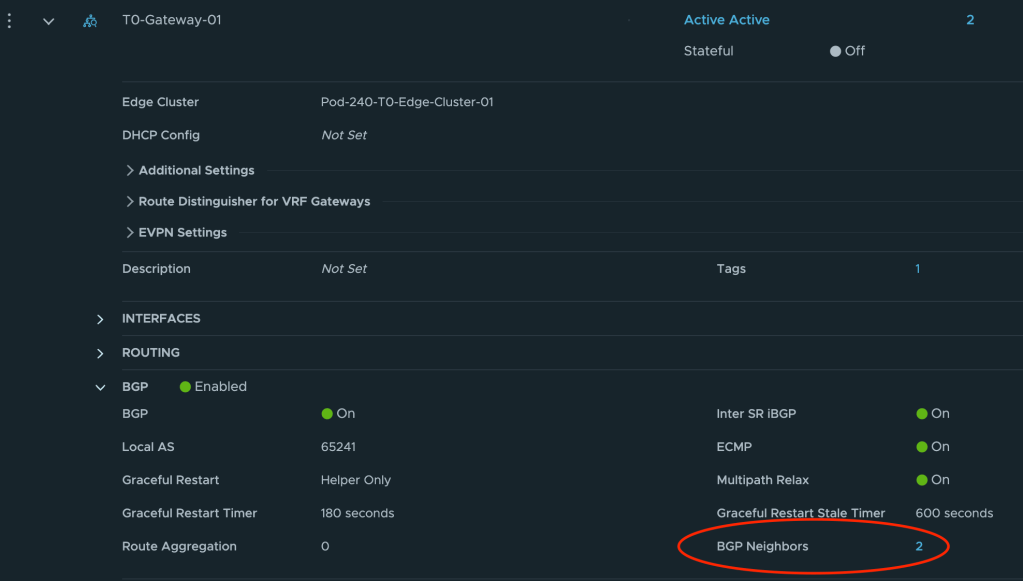
The Tier-0 needs to announce (for VyOS) that it is capable of doing L2VPN EVPN. To configure this we navigate to Networking > Tier-0 Gateways and expand the Tier-0 gateway. Click on or expand BGP and click the number to the right of BGP Neighbors.
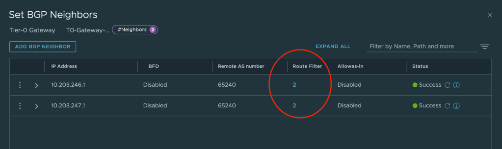
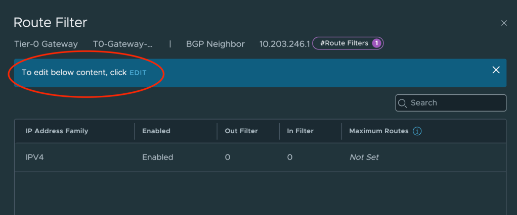
In the Set BGP Neighbors dialog you’ll see the BGP neighbor entries. For each entry click on the number in the Route Filter column.
This will bring up a new dialog where we can edit the route filter once we’ve clicked on Edit.
We can now click on Add Route Filter and add L2VPN EVPN to the filter. We leave all other settings as they are.
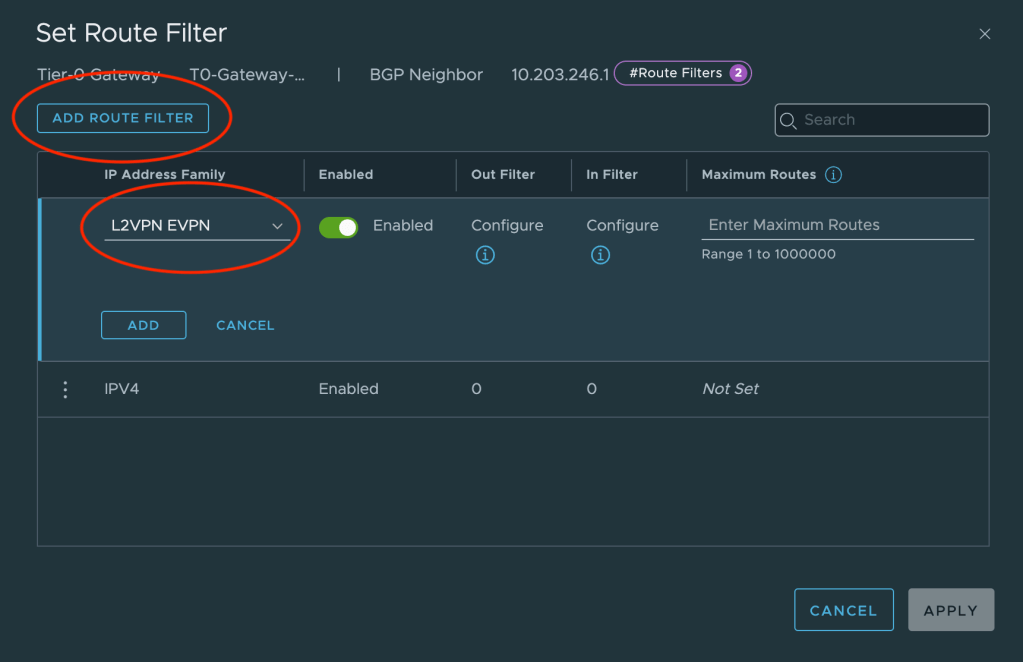
Repeat this configuration for the other neighbor entry.
EVPN Settings
Some specific EVPN settings are required and these settings are found under EVPN Settings.
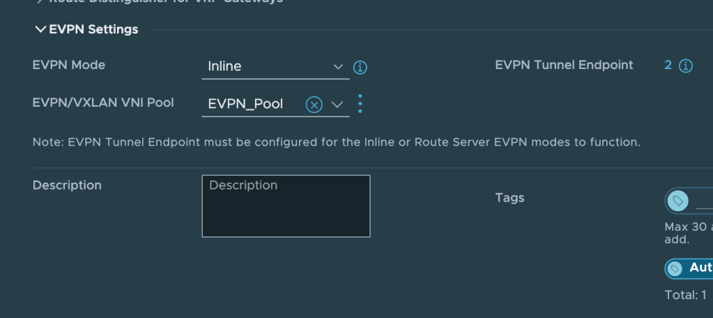
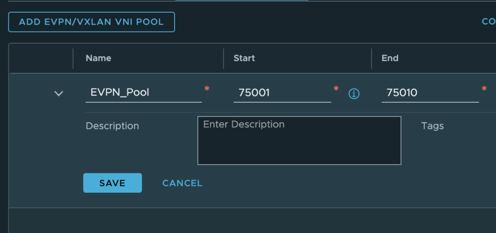
Click Edit on the Tier-0 gateway and change the EVPN Mode to Inline. Next create a new EVPN/VXLAN VNI Pool. As per the table above the VNI range will be from 75001 to 75010.
The last thing we need to configure under EVPN Settings is EVPN Tunnel Endpoint. These are the IP addresses for the VXLAN TEP interfaces that will be instantiated on the edge nodes. Each edge node will have its own TEP interface.
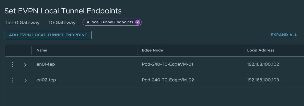
The IP addresses for these TEPs are taken from the “dummy/loopback” CIDR documented in the table above. We configure 192.168.100.102 for edge node 1 and 192.168.100.103 for edge node 2. These IP addresses don’t belong to any existing VLAN or overlay segment and need to be advertised to the VyOS router.
Route Re-distribution
We use the existing eBGP process between the Tier-0 and the VyOS router to get the VXLAN TEP IP address out there. This is configured on the Tier-0 under Route Re-distribution.
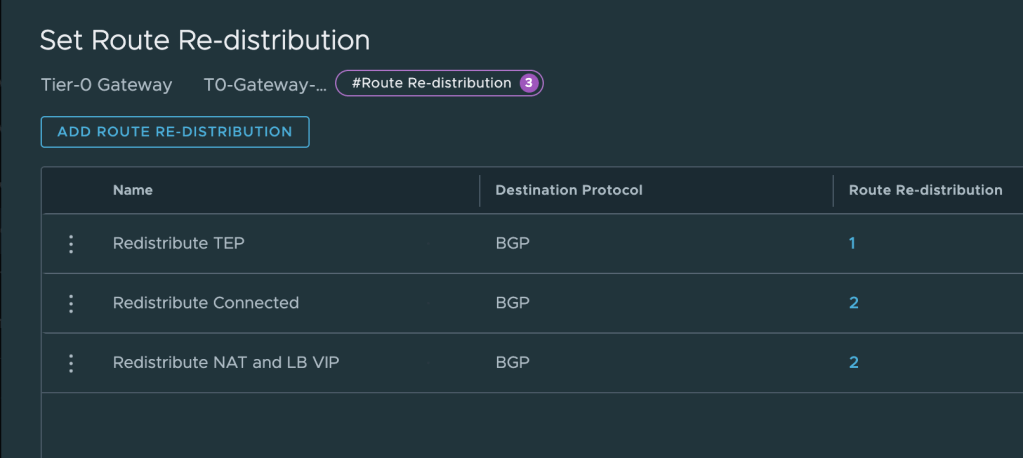
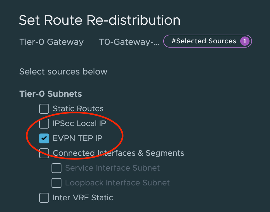
Create a new entry or update an existing one so that it includes route re-distribution for EVPN TEP IP.
Step 2 – Validate
Now that the Tier-0 gateway has been prepared for BGP EVPN, it’s a good time to verify that the VyOS router knows about the new capability and the VXLAN TEP IP addresses.
Log in to the VyOS router and run the following command:
show bgp neighbors
This command will give us details about each BGP neighbor configured. We’re specifically interested in what is listed under Neighbor capabilities:

As we can see in the screenshot above the L2VPN EVPN capability is advertised and received . Now let’s have a quick look at the routing table:
show ip route bgp
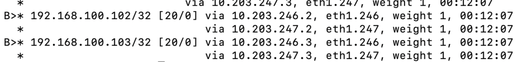
We can see that the configured VXLAN TEP IP addresses on our edge nodes are in the table.
Step 3 – Create VRF Gateways
Each tenant gets its own NSX VRF gateway and now is the time to create them.
Navigate to Networking > Tier-0 Gateways and click on Add Gateway. Select VRF.
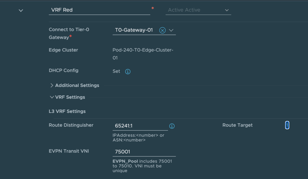
The following settings are configured for the VRF for tenant Red:
| Item | Value | Description |
| Name | VRF Red | What’s in a name? |
| Connect to Tier-0 Gateway | T0-Gateway-01 | The parent Tier-0 gateway |
| VRF Settings > Route Distinguisher | 65241:1 | Distinguishes routes coming from this VRF |
| VRF Settings > EVPN Transit VNI | 75001 | The VXLAN VNI this VRF will use |
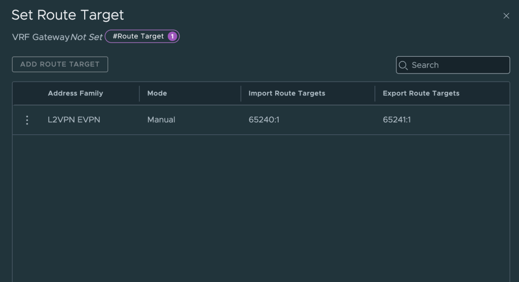
| VRF Settings > Route Target > Import Route Targets | 65240:1 | Import routes with this route distinguisher from VyOS |
| VRF Settings > Route Target > Export Route Targets | 65241:1 | Export routes with this route distinguisher to VyOS |
The following settings are configured for the VRF for tenant Blue:
| Item | Value | Description |
| Name | VRF Blue | |
| Connect to Tier-0 Gateway | T0-Gateway-01 | The parent Tier-0 gateway |
| VRF Settings > Route Distinguisher | 65241:2 | Distinguishes routes coming from this VRF |
| VRF Settings > EVPN Transit VNI | 75002 | The VXLAN VNI this VRF will use |
| VRF Settings > Route Target > Import Route Targets | 65240:2 | Import routes with this route distinguisher from VyOS |
| VRF Settings > Route Target > Export Route Targets | 65241:2 | Export routes with this route distinguisher to VyOS |
Besides this we also need to make sure that we re-distribute Tier-1 gateway connected segments into the BGP. For this we create a Route Re-distribution that contains Advertised Tier-1 Subnets > Connected Interfaces & Segments on each of the VRFs.
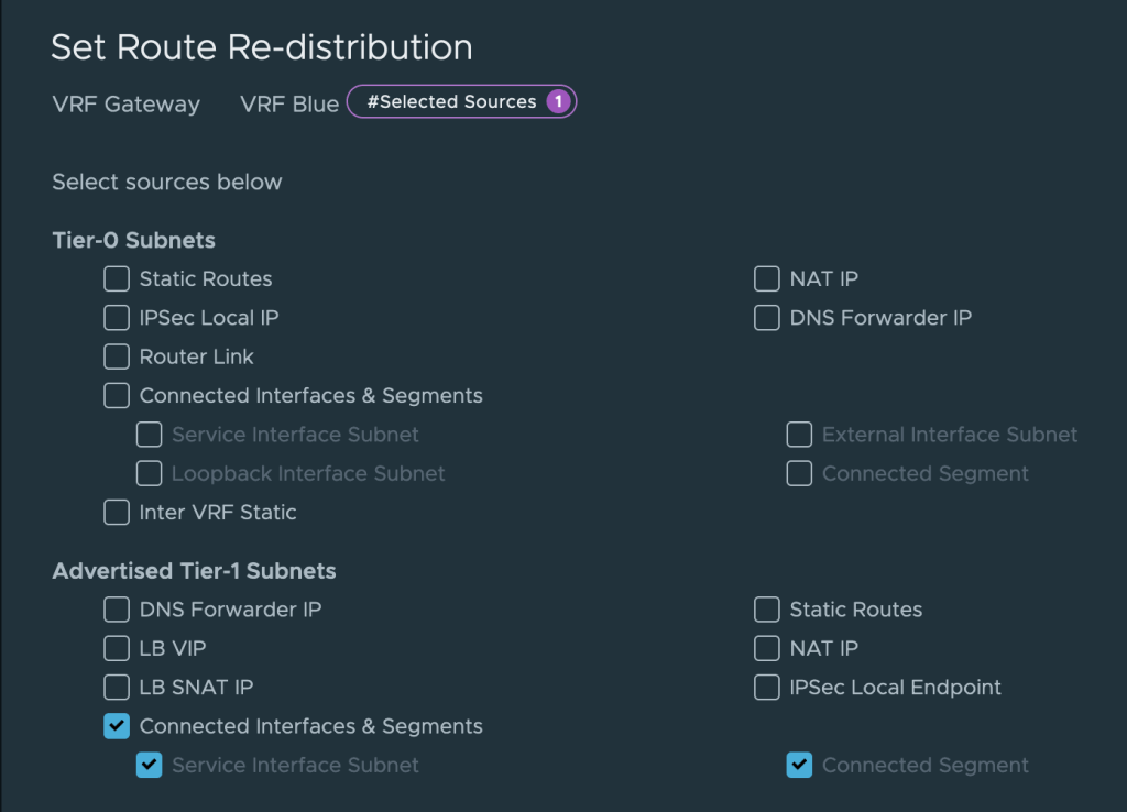
This completes the creation and configuration of the VRF gateways for our tenants.
Step 4 – Create Tier-1 Gateways
To make use of the native data plane multi-tenancy offered within NSX, each tenant receives a Tier-1 gateway with an uplink to its VRF and downlink(s) to the tenant’s overlay segment(s).
The table below shows the settings that are configured for the Tier-1 for tenant Red:
| Item | Value | Description |
| Name | Tier-1 Red | |
| HA Mode | Distributed Only | This Tier-1 will only exist in RAM. |
| Linked Tier-0 Gateway | VRF Red | The tenant’s VRF gateway |
| Route Advertisement | All Connected Segments & Service Ports | The tenant’s segments are advertised toward the VRF |
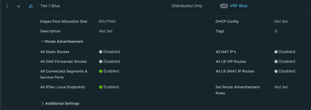
And below the settings configured for the Tier-1 for tenant Blue:
| Item | Value | Description |
| Name | Tier-1 Blue | |
| HA Mode | Distributed Only | This Tier-1 will only exist in RAM. |
| Linked Tier-0 Gateway | VRF Blue | The tenant’s VRF gateway |
| Route Advertisement | All Connected Segments & Service Ports | The tenant’s segments are advertised toward the VRF |
Step 4 – Create Segments
Lastly, each tenant receives a logical layer 2 segment to which the tenant’s workloads can be connected.
The table below shows the settings configured for tenant Red’s segment
| Item | Value | Description |
| Name | Segment Red | |
| Connected Gateway | Tier-1 Red | Downlink from the tenant’s Tier-1 |
| Transport Zone | TZ-Overlay | The overlay transport zone |
| Subnets | 10.204.245.1/24 | The CIDR and IP gateway for this segment |
The table below shows the settings configured for tenant Blue’s segment
| Item | Value | Description |
| Name | Segment Blue | |
| Connected Gateway | Tier-1 Blue | Downlink from the tenant’s Tier-1 |
| Transport Zone | TZ-Overlay | The overlay transport zone |
| Subnets | 10.204.246.1/24 | The CIDR and IP gateway for this segment |
With the segments in place let’s have a look at the Network Topology in NSX.
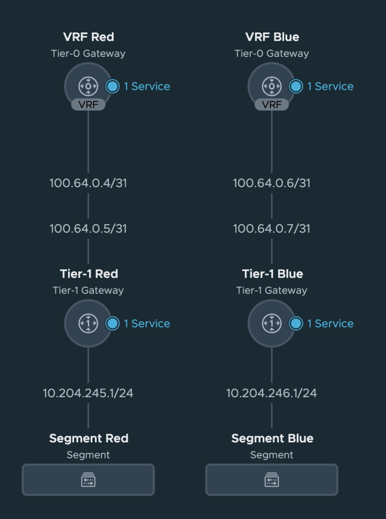
Nothing unexpected here but it’s always nice to get some visual feedback that things are connected the way they should.
Summary
At this point our NSX environment is prepared to participate in a BGP EVPN control and data plane. Configuring this has been relatively straightforward if you ask me.
In part 2 we will configure the VyOS router, establish a BGP EVPN control plane between NSX and VyOS, and validate that we have accomplished our task of separating and isolating tenant network traffic from NSX overlay to data center VLAN.
Thanks for reading.

Leave a comment