
Welcome back! I’m in the process of setting up NSX-T in a stretched cluster environment.
In part 1 I deployed the NSX manager cluster and configured the ESXi hosts as NSX transport nodes. The N-VDS was installed on the ESXi hosts and their vmkernel adapters migrated from the VDS to the N-VDS.
In this second part I will configure the NSX data plane for north-south and east-west networking. Again, there’s a lot to do so let’s begin!
The lab environment
A couple of things happened since the last time I had a look at the lab environment’s diagram:

The vSphere management cluster is now also hosting an NSX manager cluster and the ESXi hosts turned into NSX-T transport nodes.
Speaking of ESXi hosts, here’s a little closer look at one of them:

There’s now an N-VDS instead of a VDS with the three vmkernel adapters Management, vMotion, and vSAN. There are also two new vmkernel adapters which are acting as tunnel endpoints (TEPs) for the NSX overlay networking (geneve encapsulation/decapsulation).
The infrastructure for east-west networking is largely in place, but without a north-south network path this cluster is pretty isolated.
NSX Edge
The NSX Edge provides a central entrance/exit point for network traffic entering and exiting the SDDC and is exactly what this environment needs.
Deploy edge VMs
I’m deploying a total of four edge VMs (two at each site). I’ll deploy them using the Edge VM OVA package so that I can connect the edge node’s management interface to the NSX-T segment at the time of deployment.
The table below contains the deployment details for the edge VMs:
| Setting | en01-a | en01-b | en02-a | en02-b |
|---|---|---|---|---|
| Name | en01-a | en01-b | en02-a | en02-b |
| Network 0 | site-a-nvds01-management | site-b-nvds01-management | site-a-nvds01-management | site-b-nvds01-management |
| Network 1 | edge-uplink1 | edge-uplink1 | edge-uplink1 | edge-uplink1 |
| Network 2 | edge-uplink2 | edge-uplink2 | edge-uplink2 | edge-uplink2 |
| Network 3 | not used | not used | not used | not used |
| Mgmt IP | 172.16.41.21/24 | 172.16.51.21/24 | 172.16.41.22/24 | 172.16.51.22/24 |
Deploying the edge VM using the OVA package:

Configure edge nodes
After deployment the edge nodes need to join the management plane. For this I use the “join management-plane” NSX CLI command:

Once he edge nodes have joined the management plane, I can pick them up in the NSX Manager UI to configure each of them as Edge Transport Nodes. I’m using the following configuration details for this :
| Setting | en01-a | en01-b | en02-a | en02-b |
|---|---|---|---|---|
| Transport Zones | tz-vlan, tz-overlay | tz-vlan, tz-overlay | tz-vlan, tz-overlay | tz-vlan, tz-overlay |
| N-VDS Name | nvds01 | nvds01 | nvds01 | nvds01 |
| Uplink Profile | up-site-a-edge | up-site-b-edge | up-site-a-edge | up-site-b-edge |
| IP Assignment | Use Static IP List | Use Static IP List | Use Static IP List | Use Static IP List |
| Static IP List | 172.16.49.30,172.16.49.31 | 172.16.59.30,172.16.59.31 | 172.16.49.32,172.16.49.33 | 172.16.59.32,172.16.59.33 |
| Virtual NICs | fp-eth0 – uplink-1, fp-eth1 – uplink-2 | fp-eth0 – uplink-1, fp-eth1 – uplink-2 | fp-eth0 – uplink-1, fp-eth1 – uplink-2 | fp-eth0 – uplink-1, fp-eth1 – uplink-2 |
Edge transport nodes are managed under System > Fabric > Nodes > Edge Transport Nodes.

Like the ESXi hosts, all four edge nodes are now fully configured transport nodes:

Edge cluster
The edge transport nodes need to be part of an edge cluster. I will create an edge cluster called edge-cluster01 and add all four nodes to this cluster.
Edge clusters are managed under System > Fabric > Nodes > Edge Clusters:

Anti-affinity rules
The edge VMs shouldn’t be running on the same ESXi host. To prevent this from happening I create two anti-affinity rules on the vSphere cluster; one for the edge VMs at Site A and another for the edge VMs at Site B:

Groups and rules
The edge VMs should also stick to their site. For this I create two host and a two VM groups. A “virtual machine to host” rule will then make sure that the edge VMs stay pinned to their respective site.
The host group for Site A:

The VM group for the edge VMs at Site B:

The “virtual machine to host” rule keeping edge VMs belonging to Site A on the ESXi hosts of Site A:

The result of having these groups and rules in place becomes visible after some seconds. Edge VMs are running at the correct site and on seperate ESXi hosts within a site:

That pretty much completes the NSX Edge infrastructure deployment in my stretched cluster.
Routing
Now that the NSX-T Edge is in place, it’s time to set up a connection with the physical network so that packets can actually get in and out of the environment.
Tier-0 gateway
A Tier-0 gateway provides the gateway service between the logical and the physical network and is just what I need.
I’m creating my Tier-0 gateway with the following configuration details:
| Setting | Value |
|---|---|
| Name | tier0-01 |
| High Availability Mode | Active-Active |
| Edge Cluster | edge-cluster01 |
| Route Re-Distribution | all |
Tier-0 gateways are managed under Networking > Connectivity > Tier-0 Gateways.

Interfaces
This Tier-0 will have eight external interfaces mapped to the different edge transport nodes at the two sites. The table below shows the interfaces and their configuration details:
| Name | IP Address / Mask | Connected To | Edge Node | MTU |
|---|---|---|---|---|
| en01-a-uplink01 | 172.16.47.2/24 | site-a-edge-transit01 | en01-a | 9000 |
| en01-a-uplink02 | 172.16.48.2/24 | site-a-edge-transit02 | en01-a | 9000 |
| en02-a-uplink01 | 172.16.47.3/24 | site-a-edge-transit01 | en02-a | 9000 |
| en02-a-uplink02 | 172.16.48.3/24 | site-a-edge-transit02 | en02-a | 9000 |
| en01-b-uplink01 | 172.16.57.2/24 | site-b-edge-transit01 | en01-b | 9000 |
| en01-b-uplink02 | 172.16.58.2/24 | site-b-edge-transit02 | en01-b | 9000 |
| en02-b-uplink01 | 172.16.57.3/24 | site-b-edge-transit01 | en02-b | 9000 |
| en02-b-uplink02 | 172.16.58.3/24 | site-b-edge-transit02 | en02-b | 9000 |
The Tier-0 external interfaces are now configured and active:

BGP
The TORs have been configured for BGP already and now I need to set up BGP at the Tier-0 gateway too.
The BGP settings that I will use on the Tier-0 gateway are:
| Setting | Value |
|---|---|
| Local AS | 65000 |
| BGP | On |
| Graceful Restart | Off |
| Inter SR iBGP | On |
| ECMP | On |
| Multipath Relax | On |
Configuring BGP details on the Tier-0 gateway:

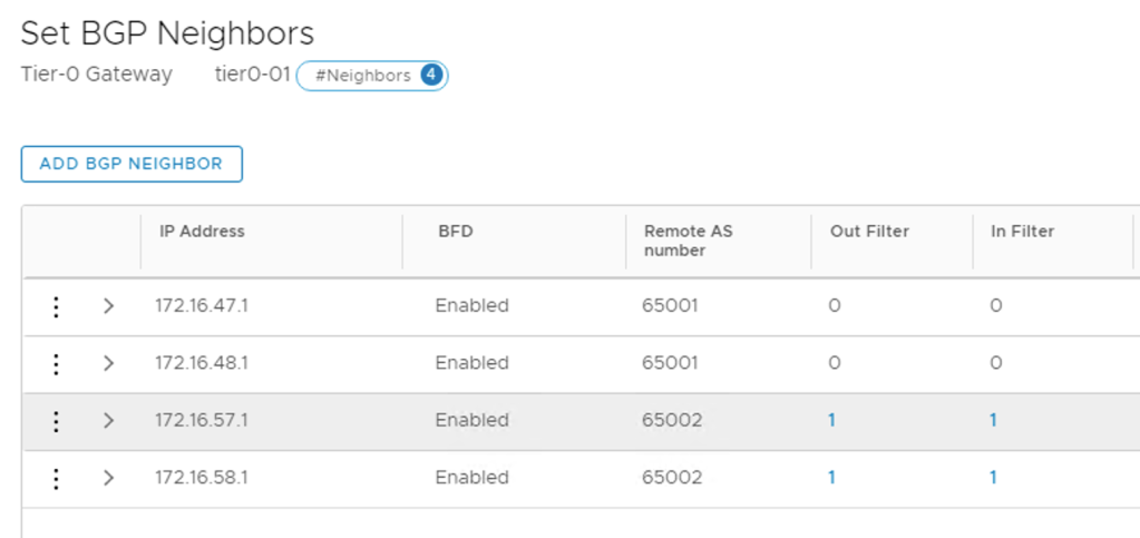
I’m adding each TOR as a BGP neighbor to the Tier-0 gateway. The following table shows the configuration details for the four BGP neighbor entries:
| IP address | BFD | Remote AS | Hold Down | Keep Alive |
|---|---|---|---|---|
| 172.16.47.1 | Enabled | 65001 | 12 | 4 |
| 172.16.48.1 | Enabled | 65001 | 12 | 4 |
| 172.16.57.1 | Enabled | 65002 | 12 | 4 |
| 172.16.58.1 | Enabled | 65002 | 12 | 4 |
The BGP neighbor status after the four TORs are added:

Route map
To prevent asymmetric traffic flows, the NSX Edge infrastructure at Site A should be the preferred ingress/egress point for the north-south traffic.
I achieve this by AS path prepending on the BGP paths to Site B. This is configured in a route map on the Tier-0 gateway.
First I need to create an IP prefix list. Both IP prefix lists and route maps are managed on the Tier-0 gateways under Routing:

The details of the IP prefix list:
| Setting | Value |
|---|---|
| Name | any-prefix |
| Network | any |
| Action | Permit |
The details of the route map:
| Setting | Value |
|---|---|
| Route Map Name | siteb-route-map |
| Type | IP Prefix |
| Members | any-prefix |
| AS path prepend | 65000 65000 |
The route map needs to be attached to the BGP neighbor entries belonging to Site B. I configure the route map as Out Filter and In Filter:

The Site B neighbors now have filters configured:
This completes the Tier-0 gateway deployment.
Diagram
I’m just taking a step back to have a look at what it is I actually did here.
The diagram below shows the Tier-0 gateway’s L3 connectivity with the physical network:

It’s a pretty wild diagram I’m aware, but hopefully it makes some sense.
East-West
The Tier-1 gateway is where the NSX-T segments for virtual machine networking will be connected. The Tier-1 gateway is linked to the Tier-0 gateway too, of course.
I’m creating a Tier-1 gateway with the following configuration details:
| Setting | Value |
|---|---|
| Name | tier1-01 |
| Linked Tier-0 Gateway | tier0-01 |
| Fail Over | Non Preemptive |
| Edge Cluster | edge-cluster01 |
| Route Advertisement | all |
Tier-1 gateways are managed under Networking > Connectivity > Tier-1 Gateways.

Workload segments
With the Tier-1 gateway in place I can now attach some NSX-T segments for the workloads (VMs).
I’m creating three segments Web, App, and DB with the following configuration details:
| Setting | Value |
|---|---|
| Connected Gateway & Type | tier1-01, flexible |
| Transport Zone | tz-overlay |
| Subnets (gateway) | 10.0.1.1/24 (Web), 10.0.2.1 (App), 10.0.3.1 (DB) |
Creating the segments:

I notice that downlink ports have been created on the Tier-1 gateway:

Provision VMs
It’s all about the VMs of course. So I deploy three VMs web01, app01, and db01. They are connected to the segments.
VM web01 connected to segment Web as seen at the N-VDS Visualization in the NSX Manager UI:

Connectivity test
Time to test connectivity.
East-west
First between the VMs which I place on different ESXi hosts and at different sites.
web01 (10.0.1.10) at Site B pinging db01 (10.0.3.10) at Site A:

Visualized by the Port Connection tool in the NSX Manager UI:

app01 (10.0.2.10) at Site A pinging web01 at Site B:

Once again visualized by the Port Connection tool:

East-west and cross-site logical networking seems to be working!
North-south
How about north-south? Let’s see.
db01 at Site A pinging a host on the physical network (10.2.129.86):

The Traceflow tool in the NSX Manager UI tells me a bit more about the network path. I can see that the traffic exits the SDDC through Site A (en02-a):

The other way around a traceroute from the physical network to web01 at Site B:

Traffic entering the SDDC through Site A (en01-a). Perfect!
Summary
Wow! This has been quite an exercise. Are you still there? 😉
It all started with deploying the NSX Edge (virtual) infrastructure. On top of that infrastructure I deployed a Tier-0 gateway and configured dynamic routing between the Tier-0 and the TORs.
To facilitate for east-west distributed logical networking, I deployed a Tier-1 gateway and linked it to the Tier-0. I connected some NSX-T segments to the Tier-1 gateway and some virtual machines to the segments.
Some simple connectivity testing showed that north-south and east-west networking were working as intended. Site A is consistently used for the north-south ingress/egress traffic flows thanks to the BGP AS prepending.
Thanks for staying tuned this long. I hope this and the previous article about deploying NSX-T in a stretched cluster environment have been interesting reads. I might return to this environment for some more NSX-T multisite scenarios in future articles.
Cheers!

Hi,
You have deployed completely on the Site A and Site B , but what about the Witness site . For the witness site the reach-ability be from traditional network or we can implement it on the NSX-T.
Just curious to know.
Thank you
LikeLike
Hi Manoj,
NSX-T was not deployed at the witness site as it was a site dedicated for the witness functionality.
Thank you for reading my blog.
Rutger
LikeLike
Hi
Thank you for the really nice blog! As I understand you route everything over the DCI except the SDDC Management VLAN, this one is really streched between both sites (L2), right?
Where do you attach the two Host-Overlay vlans, vmotion vlans and esx vlans for routing between the to datacenter sites in real world?
Thanks for help
LikeLike
Thanks for reading my blog.
It will depend on your network topology but with a leaf-spine topology these VLANs would be terminated in the leaves (ToRs) and traffic routed to a spine. From that spine traffic would then be routed to the leaf where the destination host is connected.
Hope this makes sense.
LikeLike
Thanks for clarification but then for me its unclear why you split the esxi per site into different vlans?
You really want to route the HA traffic between the datacenters? Isnt it the better way to just move all esxi which are on the same vcenter per site into the same vlan?
LikeLike
In this case the scenario is a stretched cluster. There will be some traffic (L3 and L2) crossing the data center interconnect as a result of that design. The primary reason for using different VLANs per site is to create smaller layer 2 fault domains.
On a side note this is a vSAN stretched cluster and HA traffic goes over the vSAN network.
LikeLike
Hi, thanks for your brilliant guide on stretched clusters. One thing that is still puzzling me is say for example CustomerA had a presence at Site A with some VM’s and they also have some VM’s at Site B, is it possible for these customer VM’s to be on the same subnet? I’m just thinking from a failure scenario of the Site A hardware or a loss of the hardware at Site A for whatever reason – of course they would need the relevant vSAN policy applied to be able to tolerate this level of failure.
Any ideas would be much appreciated.
Thanks
LikeLike
Thanks Richard,
The VMs can be on the same logical network regardless of on which site they’re running. This is accomplished using Geneve overlay in NSX-T.
LikeLike
Hi,
The North-South trace shows Site-B Tier-0 in the path. Is there a reason for that? Also the VMware documentation says with active-active setup Tier-0 plums to all the Edge nodes in a cluster with ECMP. Can that be overcome with inbound as-path prepend that you have applied?
Thank you.
LikeLike
Hi,
The traceflow was done from a VM on site B. I realize that wasn’t clear at all.
By AS-path prepending at site B, inbound traffic will enter through site A (under normal circumstances).
Cheers
LikeLike
Hi,
briliant work, thx…
Do you have plans to update this lab solution with newest version of NSX 3.1
I have plans to deploy NSX-T 3.1 to the prod system with existing vSAN 7 with stretched cluster.
So, it has VDS 6.6 and where is no any management cluster, so just one consolidated compute cluster with management components like vCenter, NSX management cluster and Edge must be implimented with a 10 ESXi hosts.
Any suggestions welcome…
LikeLike
Thanks. That should be fine. Any reason the VDS is still on 6.6? How many pNICs do your host have?
LikeLike
Is there any supported way to configure local egress in stretched clusters. For Example : traffic from a VMin site be to a physical server in site be should be in and out through tor in site b
LikeLike
With NSX-T Multisite it’s only possible when you have distinct logical networks in each site. If the logical network is stretched, local egress can not ne enforced. With NSX-T Federation you can configure local egress by making the T0 “Primary” in each location.
LikeLike
Thanks for the blog post, very helpful. Because the T0 is configured in ECMP will the traffic not traverse all links within the edge cluster regardless of the site?
LikeLike
Hi Ben. With this particular set up that’s indeed the case for traffic from NSX to the physical network. Incoming traffic will be routed to the site with the shortest BGP AS path. If you would also like to pin the outgoing traffic to a certain site you can do so by using route priorities.
LikeLike
Hi Rutger, thanks for a very good guide on this. We are deploying a VCF solution and are having trouble understanding where to route the vSAN and vMotion VLANs. Is your suggestion to do this L3-routing in the ToR instead of doing it through NSX overlay?
LikeLike
Thanks Andreas.
This will be dictated by VCF and depends on the version of VCF you are deploying and some of the design decisions. In the latest versions you will have everything routed except for the management network which is still stretched. So with VCF, regardless of what you and I think is the best way of doing it, it’s very important to stick to that intended design for supportability reasons.
Cheers
LikeLike
Hi Rutger,
Thank you for the Explanation. We have been trying to get the same type of configuration running but have hit into a few issues however unsure if they are related to the newer NSX-T version 3.1.1 we are running or if we are missing something.
Outbound
Advertising the routes out bound with a prepend from Site B seems to be working as expected meaning inbound to Tier 1 is going via Site A as expected. under normal circumstances and fails over to B in event of DR.
Inbound
We are advertising a default route from the upstream platform and can see that the route map is adding the prepends via the uplinks on Site B increasing the Path but this dose not seem to permit the route over the ISR to be installed. As long as a peer is up in Site B the default route is being learnt over it:
> * 0.0.0.0/0 [20/0] via A.B.C.D, uplink-277
if we actively remove the Site B peering we then see the Default routes coming over the isr:
isr> * 0.0.0.0/0 [200/0] via 169.254.0.130, inter-sr-275, 00:00:05
isr> * 0.0.0.0/0 [200/0] via 169.254.0.131, inter-sr-275, 00:00:05
from the numbers we are seeing it looks like the external peering has the AD 20 vs isr 200, have you seen this in your configuration / worked around it ?
Cheers,
James
LikeLike
Hi Rutger,
Thank you for the Explanation. We have been trying to get the same type of configuration running but have hit into a few issues however unsure if they are related to the newer NSX-T version 3.1.1 we are running or if we are missing something.
Outbound
Advertising the routes out bound with a prepend from Site B seems to be working as expected meaning inbound to Tier 1 is going via Site A as expected. Under normal circumstances and fails over to B in event of DR.
Inbound
We are advertising a default route from the upstream platform and can see that the route map is adding prepends via the uplinks on Site B increasing the Path but this does not seem to permit the route over the ISR to be installed. As long as a peer is up in Site B the default route is being learnt over it:
> * 0.0.0.0/0 [20/0] via A.B.C.D, uplink-277
If we actively remove, the Site B peering we then see the Default routes coming over the isr:
isr> * 0.0.0.0/0 [200/0] via 169.254.0.130, inter-sr-275, 00:00:05
isr> * 0.0.0.0/0 [200/0] via 169.254.0.131, inter-sr-275, 00:00:05
From the numbers we are seeing it looks like the external peering has the AD 20 vs isr 200, have you seen this in your configuration / worked around it?
Cheers,
James
LikeLike
Hi James,
I’m currently investigating a similar issue in an NSX-T 3.1.1 environment (in this article NSX-T 2.5 was used). Some things have changed and might have affected the way this is configured. I will let you know.
LikeLike
Hi Rutger,
Did you manage to find a fix for 3.1 ?
LikeLike
It’s simple you have to know the BGP protocol and how attributes handled in BGP (EBGP and IBGP).
EBGP peering between different AS number
IBGP peering between same AS number
Outbound: Thats correct with as-prepend on site B peering with external AS.
Inbound: use local-pref instead of as-prepend on inbound route prefixes on site B
Mark the routes with a local-pref lower than 100 for example 90. Default is 100.
That will steer how you in your AS will exit your own AS to other AS in this case over site A if everything is up.
Highest local-pref is prefered and is local to your as and will be used in IBGP to set best route.
All your edges peering bgp (ibgp) with each other in the same as.
LikeLike
Really great article and exercise, I haven’t really managed VMware for a while, it was pretty good to catch up with the most recent on the networking aspects. Quick (dumb) architectural question: is it common for customers running Workload VMs and Edge Nodes VMs in the same ESXi hosts? Do all ESXi have at least one L0 and L1 Gw VM? How’s that distribution work in a real-life/enterprise-scale environment? I’m supposing they would have a cluster for Edge Nodes separate from regular Workload VMs, and then in this case the ESXis reserved for Workloads still run L0s and L1s? TIA
LikeLike
Great article on High Availability for multi-site environment. Trying to understand how the flow goes between the 4 Edge nodes. There are 2 in Site-A and 2 in site-B. A question about the network flow: If there is a VM at site-A that initiates North-South traffic, which Edge VM will be primarily used? Will it be any Edge VM from Site-A or it is random and we can end up from Site-B? Same when a VM initiates North-South traffic from Site-B, which site’s Edge VMs will be used? Is there anyway that we can prioritize Edge VM based on the VM’s site? It would be great if VMs at site-A always user Edge VM at that side, same for Site-B. Otherwise it means we need to route traffic from an ESXi at site-A to and Edge VM at an ESXi at Site-B and from there we go to a ToR (in Site-B) and internet. Not optimal, which is a trade-off
LikeLike