Welcome back! I’m in the process of setting up NSX-T in a stretched cluster environment.
In part 1 I deployed the NSX manager cluster and configured the ESXi hosts as NSX transport nodes. The N-VDS was installed on the ESXi hosts and their vmkernel adapters migrated from the VDS to the N-VDS.
In this second part I will configure the NSX data plane for north-south and east-west networking. Again, there’s a lot to do so let’s begin!
The lab environment
A couple of things happened since the last time I had a look at the lab environment’s diagram:
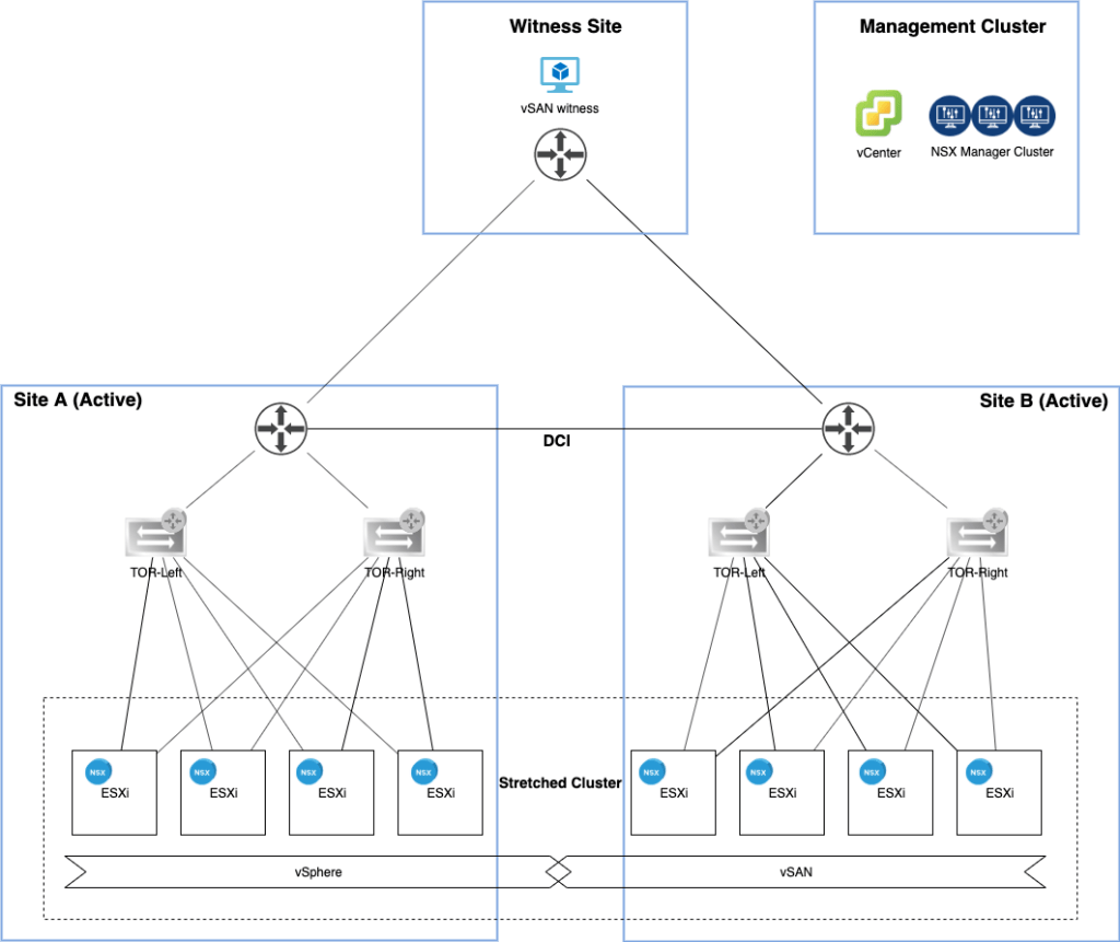
The vSphere management cluster is now also hosting an NSX manager cluster and the ESXi hosts turned into NSX-T transport nodes.
Speaking of ESXi hosts, here’s a little closer look at one of them:
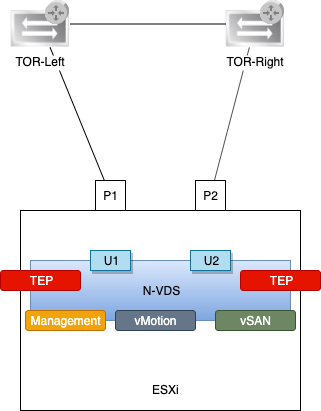
There’s now an N-VDS instead of a VDS with the three vmkernel adapters Management, vMotion, and vSAN. There are also two new vmkernel adapters which are acting as tunnel endpoints (TEPs) for the NSX overlay networking (geneve encapsulation/decapsulation).
The infrastructure for east-west networking is largely in place, but without a north-south network path this cluster is pretty isolated.
NSX Edge
The NSX Edge provides a central entrance/exit point for network traffic entering and exiting the SDDC and is exactly what this environment needs.
Deploy edge VMs
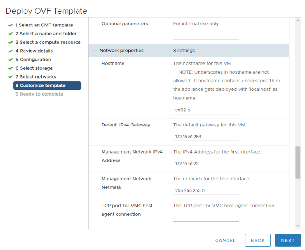
I’m deploying a total of four edge VMs (two at each site). I’ll deploy them using the Edge VM OVA package so that I can connect the edge node’s management interface to the NSX-T segment at the time of deployment.
The table below contains the deployment details for the edge VMs:
| Setting | en01-a | en01-b | en02-a | en02-b |
|---|---|---|---|---|
| Name | en01-a | en01-b | en02-a | en02-b |
| Network 0 | site-a-nvds01-management | site-b-nvds01-management | site-a-nvds01-management | site-b-nvds01-management |
| Network 1 | edge-uplink1 | edge-uplink1 | edge-uplink1 | edge-uplink1 |
| Network 2 | edge-uplink2 | edge-uplink2 | edge-uplink2 | edge-uplink2 |
| Network 3 | not used | not used | not used | not used |
| Mgmt IP | 172.16.41.21/24 | 172.16.51.21/24 | 172.16.41.22/24 | 172.16.51.22/24 |
Deploying the edge VM using the OVA package:
Configure edge nodes
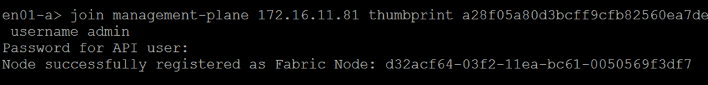
After deployment the edge nodes need to join the management plane. For this I use the “join management-plane” NSX CLI command:
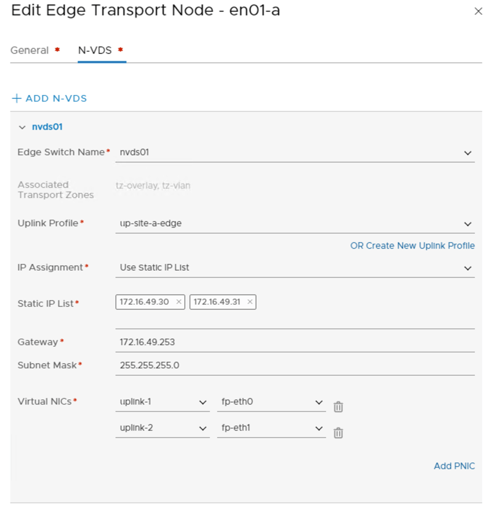
Once he edge nodes have joined the management plane, I can pick them up in the NSX Manager UI to configure each of them as Edge Transport Nodes. I’m using the following configuration details for this :
| Setting | en01-a | en01-b | en02-a | en02-b |
|---|---|---|---|---|
| Transport Zones | tz-vlan, tz-overlay | tz-vlan, tz-overlay | tz-vlan, tz-overlay | tz-vlan, tz-overlay |
| N-VDS Name | nvds01 | nvds01 | nvds01 | nvds01 |
| Uplink Profile | up-site-a-edge | up-site-b-edge | up-site-a-edge | up-site-b-edge |
| IP Assignment | Use Static IP List | Use Static IP List | Use Static IP List | Use Static IP List |
| Static IP List | 172.16.49.30,172.16.49.31 | 172.16.59.30,172.16.59.31 | 172.16.49.32,172.16.49.33 | 172.16.59.32,172.16.59.33 |
| Virtual NICs | fp-eth0 – uplink-1, fp-eth1 – uplink-2 | fp-eth0 – uplink-1, fp-eth1 – uplink-2 | fp-eth0 – uplink-1, fp-eth1 – uplink-2 | fp-eth0 – uplink-1, fp-eth1 – uplink-2 |
Edge transport nodes are managed under System > Fabric > Nodes > Edge Transport Nodes.
Like the ESXi hosts, all four edge nodes are now fully configured transport nodes:

Edge cluster
The edge transport nodes need to be part of an edge cluster. I will create an edge cluster called edge-cluster01 and add all four nodes to this cluster.
Edge clusters are managed under System > Fabric > Nodes > Edge Clusters:

Anti-affinity rules
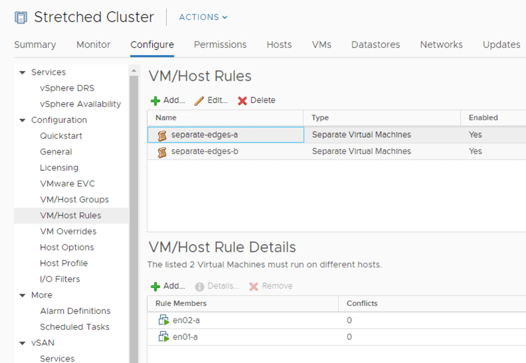
The edge VMs shouldn’t be running on the same ESXi host. To prevent this from happening I create two anti-affinity rules on the vSphere cluster; one for the edge VMs at Site A and another for the edge VMs at Site B:
Groups and rules
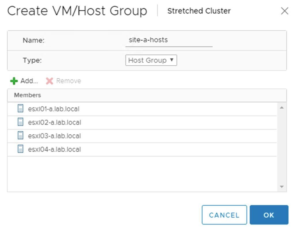
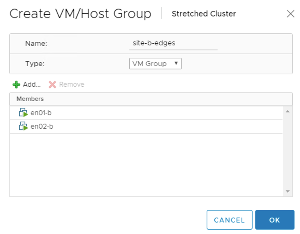
The edge VMs should also stick to their site. For this I create two host and a two VM groups. A “virtual machine to host” rule will then make sure that the edge VMs stay pinned to their respective site.
The host group for Site A:
The VM group for the edge VMs at Site B:
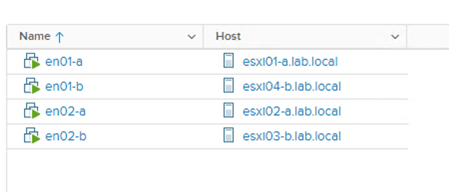
The “virtual machine to host” rule keeping edge VMs belonging to Site A on the ESXi hosts of Site A:

The result of having these groups and rules in place becomes visible after some seconds. Edge VMs are running at the correct site and on seperate ESXi hosts within a site:
That pretty much completes the NSX Edge infrastructure deployment in my stretched cluster.
Routing
Now that the NSX-T Edge is in place, it’s time to set up a connection with the physical network so that packets can actually get in and out of the environment.
Tier-0 gateway
A Tier-0 gateway provides the gateway service between the logical and the physical network and is just what I need.
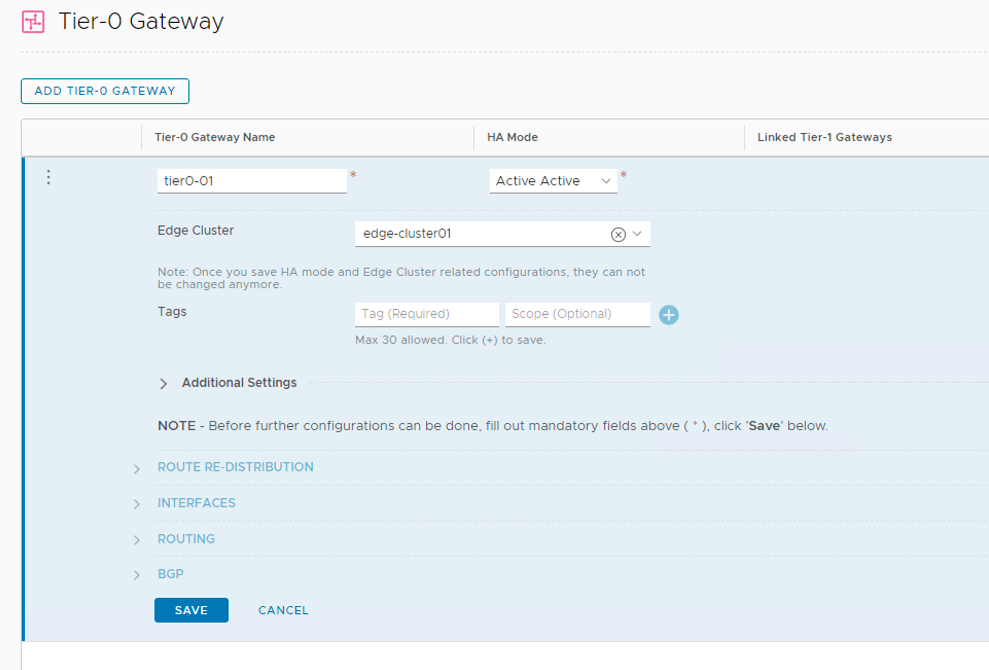
I’m creating my Tier-0 gateway with the following configuration details:
| Setting | Value |
|---|---|
| Name | tier0-01 |
| High Availability Mode | Active-Active |
| Edge Cluster | edge-cluster01 |
| Route Re-Distribution | all |
Tier-0 gateways are managed under Networking > Connectivity > Tier-0 Gateways.
Interfaces
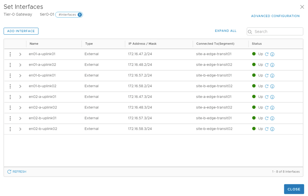
This Tier-0 will have eight external interfaces mapped to the different edge transport nodes at the two sites. The table below shows the interfaces and their configuration details:
| Name | IP Address / Mask | Connected To | Edge Node | MTU |
|---|---|---|---|---|
| en01-a-uplink01 | 172.16.47.2/24 | site-a-edge-transit01 | en01-a | 9000 |
| en01-a-uplink02 | 172.16.48.2/24 | site-a-edge-transit02 | en01-a | 9000 |
| en02-a-uplink01 | 172.16.47.3/24 | site-a-edge-transit01 | en02-a | 9000 |
| en02-a-uplink02 | 172.16.48.3/24 | site-a-edge-transit02 | en02-a | 9000 |
| en01-b-uplink01 | 172.16.57.2/24 | site-b-edge-transit01 | en01-b | 9000 |
| en01-b-uplink02 | 172.16.58.2/24 | site-b-edge-transit02 | en01-b | 9000 |
| en02-b-uplink01 | 172.16.57.3/24 | site-b-edge-transit01 | en02-b | 9000 |
| en02-b-uplink02 | 172.16.58.3/24 | site-b-edge-transit02 | en02-b | 9000 |
The Tier-0 external interfaces are now configured and active:
BGP
The TORs have been configured for BGP already and now I need to set up BGP at the Tier-0 gateway too.
The BGP settings that I will use on the Tier-0 gateway are:
| Setting | Value |
|---|---|
| Local AS | 65000 |
| BGP | On |
| Graceful Restart | Off |
| Inter SR iBGP | On |
| ECMP | On |
| Multipath Relax | On |
Configuring BGP details on the Tier-0 gateway:

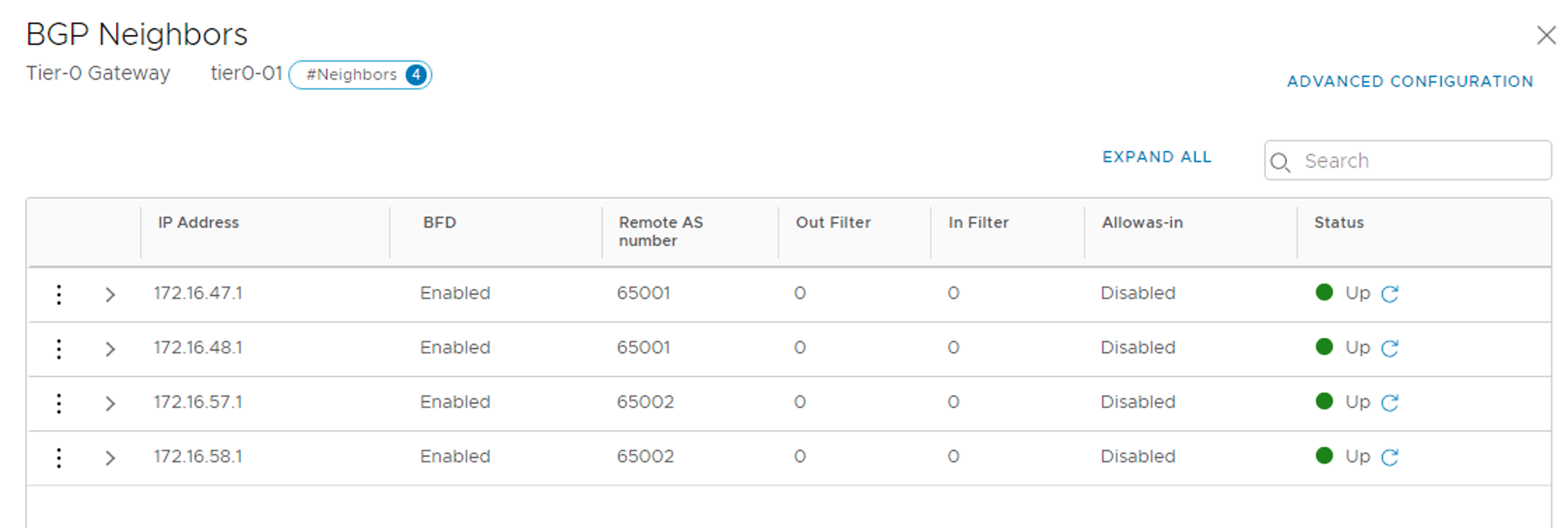
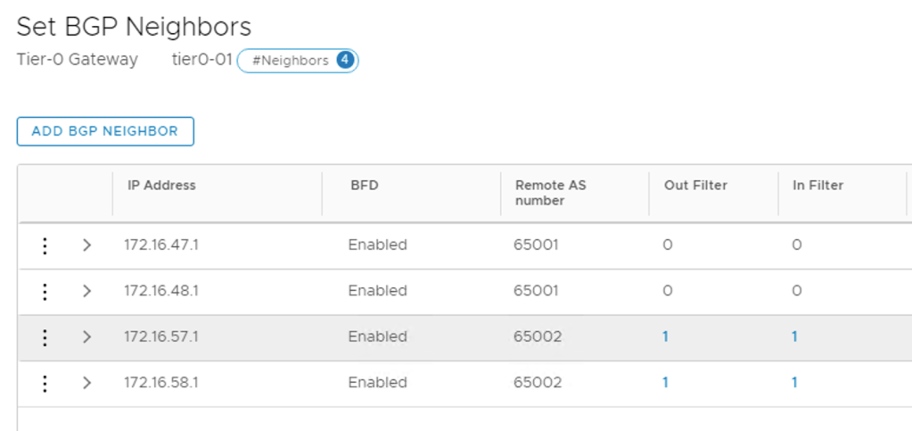
I’m adding each TOR as a BGP neighbor to the Tier-0 gateway. The following table shows the configuration details for the four BGP neighbor entries:
| IP address | BFD | Remote AS | Hold Down | Keep Alive |
|---|---|---|---|---|
| 172.16.47.1 | Enabled | 65001 | 12 | 4 |
| 172.16.48.1 | Enabled | 65001 | 12 | 4 |
| 172.16.57.1 | Enabled | 65002 | 12 | 4 |
| 172.16.58.1 | Enabled | 65002 | 12 | 4 |
The BGP neighbor status after the four TORs are added:
Route map
To prevent asymmetric traffic flows, the NSX Edge infrastructure at Site A should be the preferred ingress/egress point for the north-south traffic.
I achieve this by AS path prepending on the BGP paths to Site B. This is configured in a route map on the Tier-0 gateway.
First I need to create an IP prefix list. Both IP prefix lists and route maps are managed on the Tier-0 gateways under Routing:
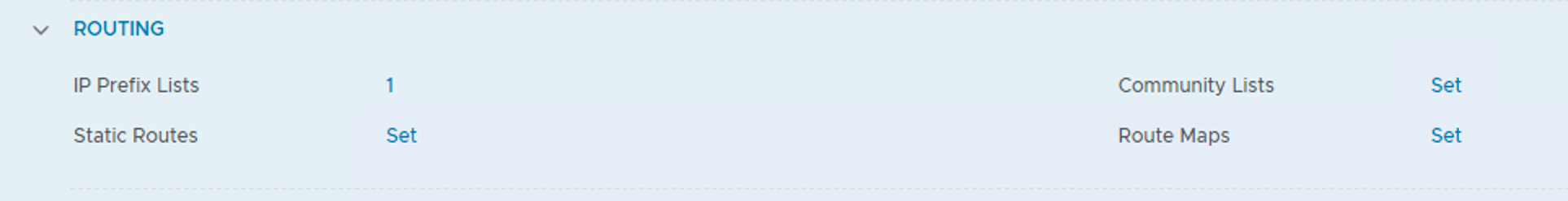
The details of the IP prefix list:
| Setting | Value |
|---|---|
| Name | any-prefix |
| Network | any |
| Action | Permit |
The details of the route map:
| Setting | Value |
|---|---|
| Route Map Name | siteb-route-map |
| Type | IP Prefix |
| Members | any-prefix |
| AS path prepend | 65000 65000 |
The route map needs to be attached to the BGP neighbor entries belonging to Site B. I configure the route map as Out Filter and In Filter:
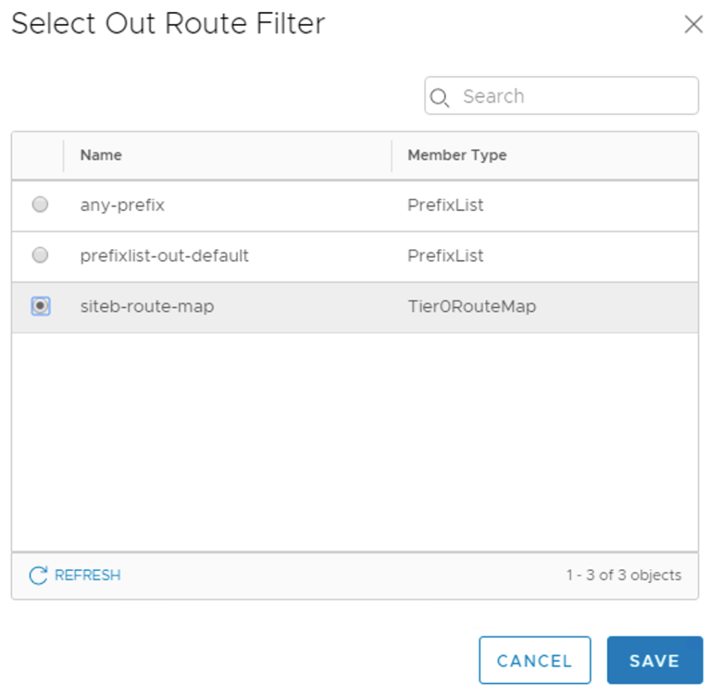
The Site B neighbors now have filters configured:
This completes the Tier-0 gateway deployment.
Diagram
I’m just taking a step back to have a look at what it is I actually did here.
The diagram below shows the Tier-0 gateway’s L3 connectivity with the physical network:
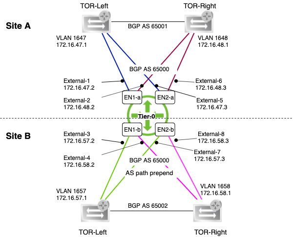
It’s a pretty wild diagram I’m aware, but hopefully it makes some sense.
East-West
The Tier-1 gateway is where the NSX-T segments for virtual machine networking will be connected. The Tier-1 gateway is linked to the Tier-0 gateway too, of course.
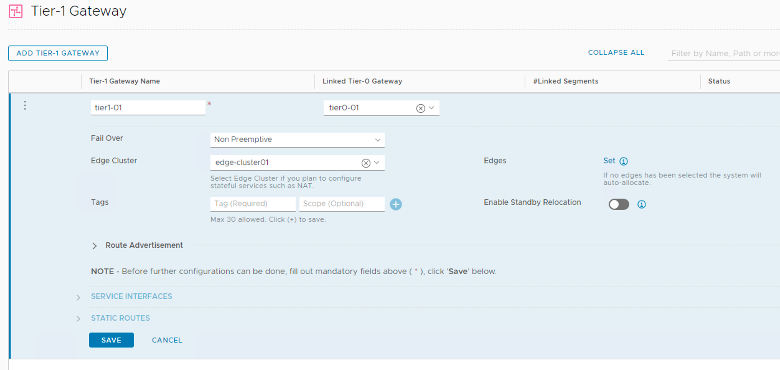
I’m creating a Tier-1 gateway with the following configuration details:
| Setting | Value |
|---|---|
| Name | tier1-01 |
| Linked Tier-0 Gateway | tier0-01 |
| Fail Over | Non Preemptive |
| Edge Cluster | edge-cluster01 |
| Route Advertisement | all |
Tier-1 gateways are managed under Networking > Connectivity > Tier-1 Gateways.
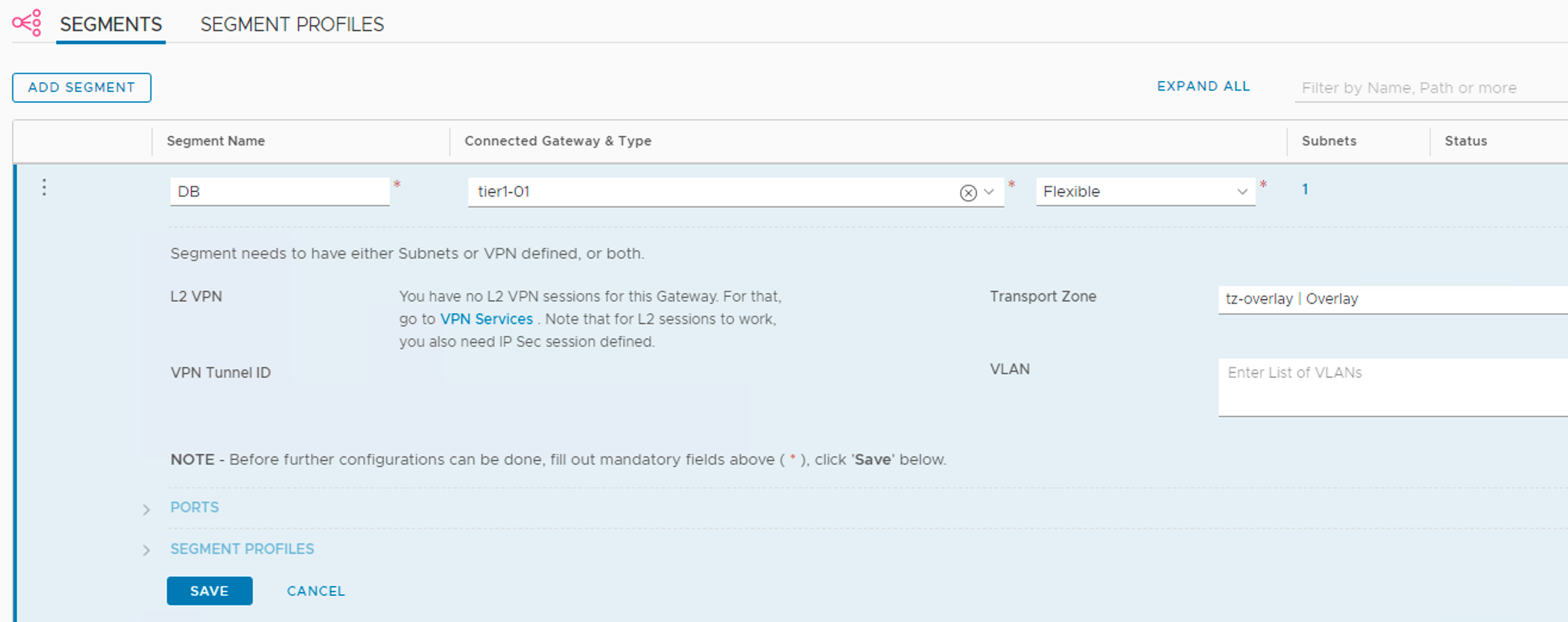
Workload segments
With the Tier-1 gateway in place I can now attach some NSX-T segments for the workloads (VMs).
I’m creating three segments Web, App, and DB with the following configuration details:
| Setting | Value |
|---|---|
| Connected Gateway & Type | tier1-01, flexible |
| Transport Zone | tz-overlay |
| Subnets (gateway) | 10.0.1.1/24 (Web), 10.0.2.1 (App), 10.0.3.1 (DB) |
Creating the segments:
I notice that downlink ports have been created on the Tier-1 gateway:

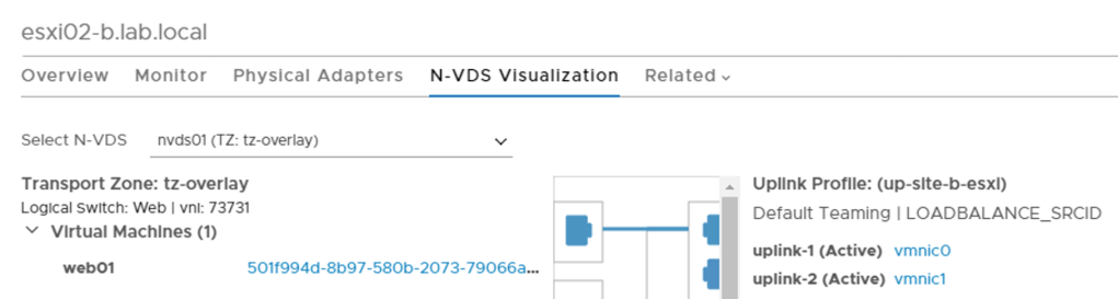
Provision VMs
It’s all about the VMs of course. So I deploy three VMs web01, app01, and db01. They are connected to the segments.
VM web01 connected to segment Web as seen at the N-VDS Visualization in the NSX Manager UI:
Connectivity test
Time to test connectivity.
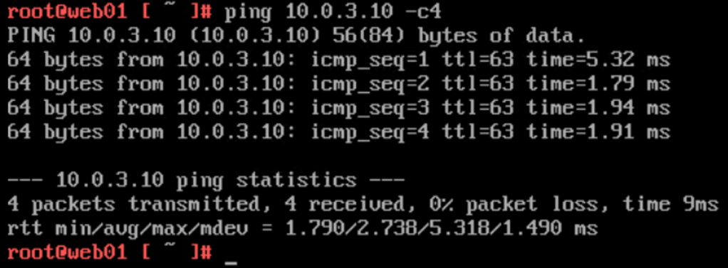
East-west
First between the VMs which I place on different ESXi hosts and at different sites.
web01 (10.0.1.10) at Site B pinging db01 (10.0.3.10) at Site A:
Visualized by the Port Connection tool in the NSX Manager UI:
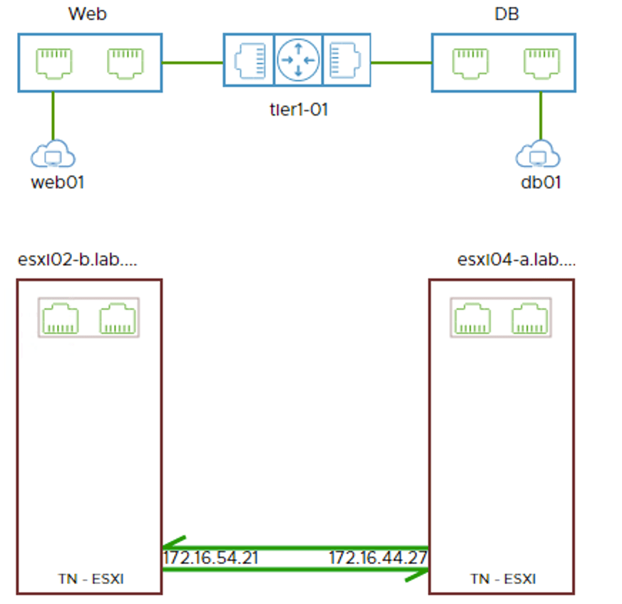
app01 (10.0.2.10) at Site A pinging web01 at Site B:
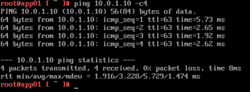
Once again visualized by the Port Connection tool:

East-west and cross-site logical networking seems to be working!
North-south
How about north-south? Let’s see.
db01 at Site A pinging a host on the physical network (10.2.129.86):
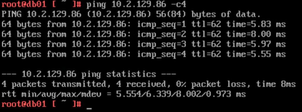
The Traceflow tool in the NSX Manager UI tells me a bit more about the network path. I can see that the traffic exits the SDDC through Site A (en02-a):
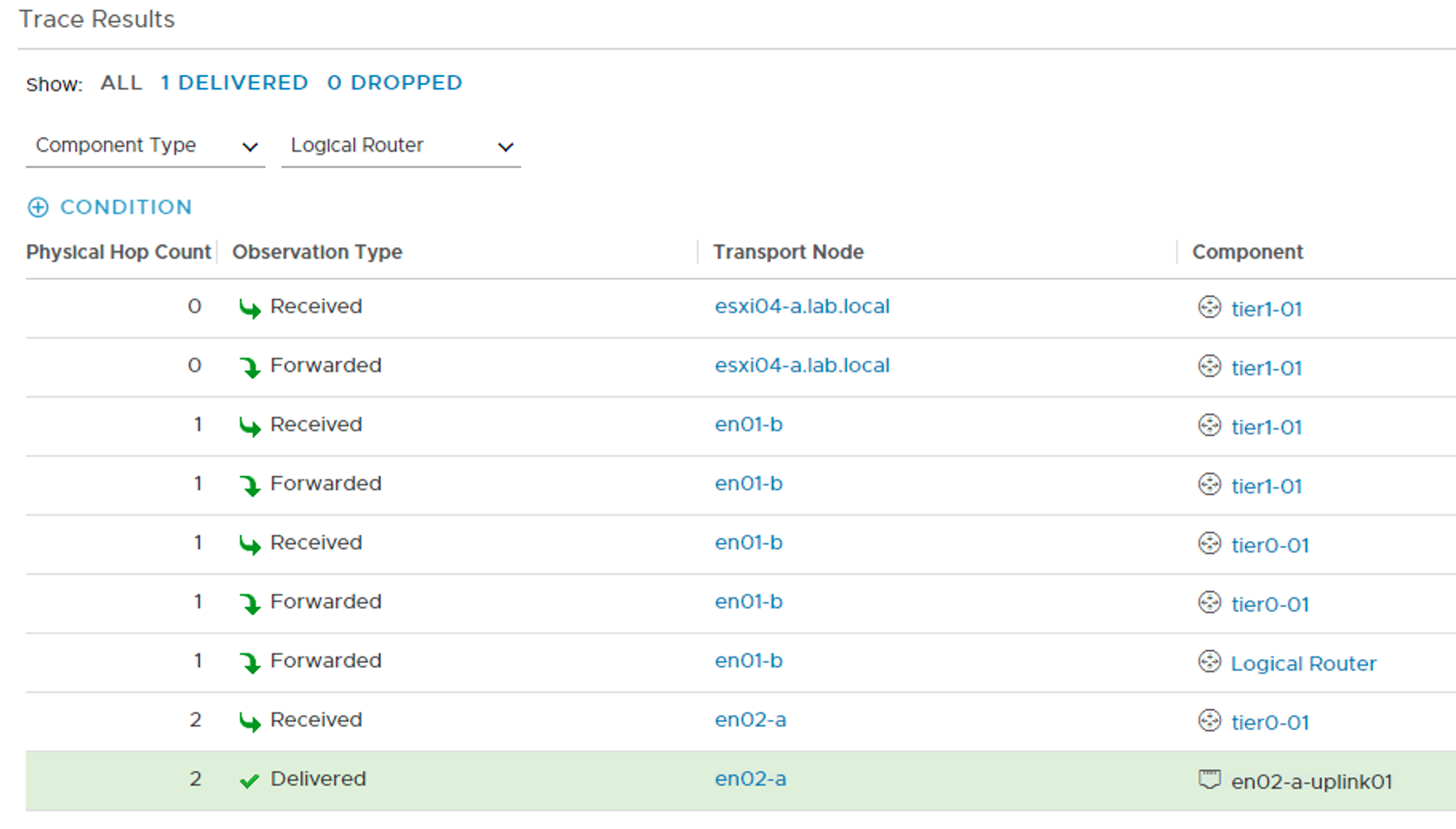
The other way around a traceroute from the physical network to web01 at Site B:
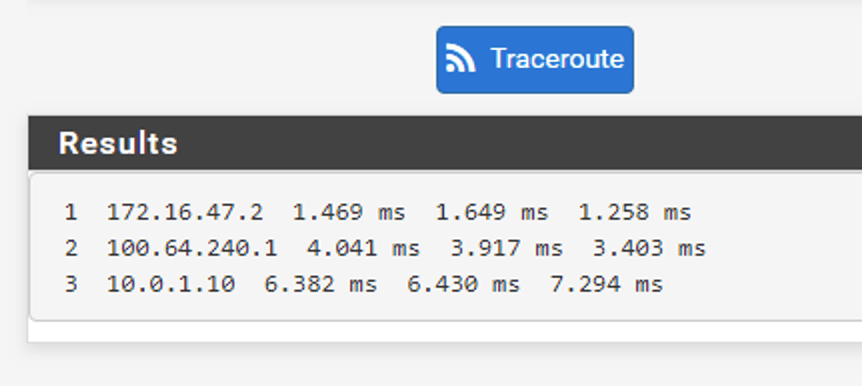
Traffic entering the SDDC through Site A (en01-a). Perfect!
Summary
Wow! This has been quite an exercise. Are you still there? 😉
It all started with deploying the NSX Edge (virtual) infrastructure. On top of that infrastructure I deployed a Tier-0 gateway and configured dynamic routing between the Tier-0 and the TORs.
To facilitate for east-west distributed logical networking, I deployed a Tier-1 gateway and linked it to the Tier-0. I connected some NSX-T segments to the Tier-1 gateway and some virtual machines to the segments.
Some simple connectivity testing showed that north-south and east-west networking were working as intended. Site A is consistently used for the north-south ingress/egress traffic flows thanks to the BGP AS prepending.
Thanks for staying tuned this long. I hope this and the previous article about deploying NSX-T in a stretched cluster environment have been interesting reads. I might return to this environment for some more NSX-T multisite scenarios in future articles.
Cheers!

Leave a comment