Happy New Year! 🙂
In the last two posts we had a look at two different methods for extending VLANs to NSX-T overlay. In the first post we configured a bridge which works well in scenarios where we the source VLAN and destination NSX-T Edge can achieve layer 2 adjacency. In the second post we configured Layer 2 VPN in a scenario where source and destination environment were completely separate and VLANs could not be stretched.
Both bridging and Layer 2 VPN achieve the same thing from the workload’s perspective: VLAN and overlay segment are one and the same meaning it can roam freely between the two, from a network perspective at least.
Bridging and Layer 2 VPN are technologies native to the NSX-T platform. Apart from some configuration you don’t need additional components to extend a VLAN into overlay. NSX-T, by design, will only provide the network infrastructure for a workload mobility solution. It (luckily) doesn’t interfere with how the workloads are being moved around.
There’s more than one solution out there that can help customers move a workload from A to B. All with their own pros and cons and often positioned for specific use cases like DC pooling, HA, DR, migration, backup, dev/test, staging, etc.
One solution that I’ve had a chance to work with in some production environments recently has shown to be exceptionally capable. Not only does it move workloads, it also considers their network connectivity and can handle different migration scenarios with that connectivity in mind.
VMware HCX
VMware HCX is a solution that is primarily used for migrating workloads between environments. Those environments can be data centers or public clouds. The solution consists of a number of services that help customers achieve workload mobility. Naturally, HCX integrates with a number of other VMware solutions and NSX-T happens to be one of them.
The main focus of today’s post will be configuring HCX network extensions between VLANs and the NSX-T overlay. This is just one use case HCX could help you with. Have a look at the HCX product documentation and check out the excellent articles at vMusketeers and HCX.Design if you are interested in learning more about the HCX solution.
The Scenario
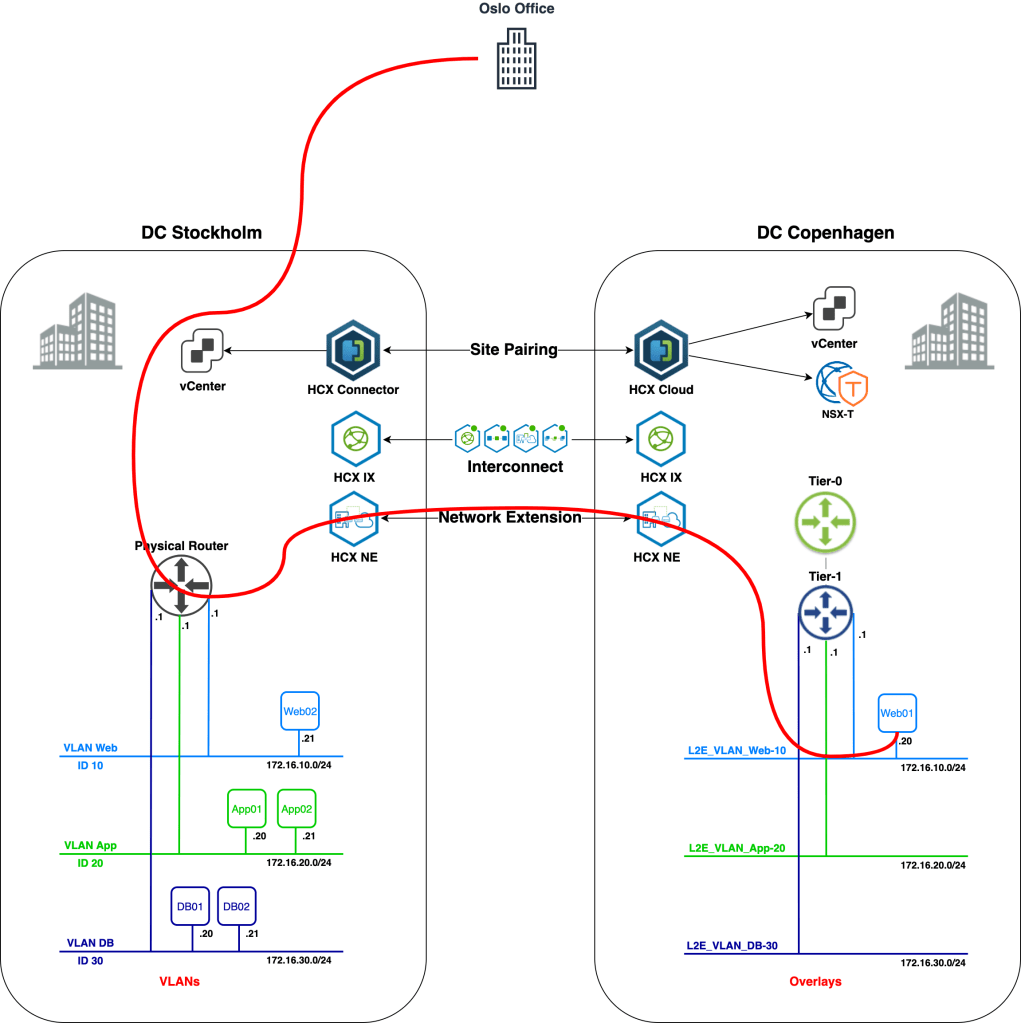
We’ll start with an overview of today’s scenario beginning with a diagram of the environment as it looks right now:

We’re finding ourselves in the middle of a data center re-location project. Virtual machines are to be migrated from a data center in Stockholm to a data center in Copenhagen. The Stockholm DC is running a vSphere-based virtual infrastructure with virtual machines connected to VLANs. The Copenhagen DC is running a fully fledged VMware SDDC and provides NSX-T overlay segments for workload connectivity.
Some preparations were made in advance. NSX-T has been deployed in the Copenhagen DC and a Tier-0 and Tier-1 Gateway are in place. HCX Manager appliances have been installed in both DCs and are connected to their respective vCenter instances and to NSX-T Manager in Copenhagen. A HCX Site Pairing has been created between the DCs:

When it comes to the actual workload migration, we are told that downtime is not an option. We won’t have access to the guest OS of the workloads, so no fiddling around in there. Using HCX, as the customer points out, we should be able to carry out this type of migration without problems. After all, the sales guy told them it would all “work like a dream”.
It’s now up to us to make the dream come true. We need to configure the HCX network extensions and carry out seamless migration of the virtual machines from Stockholm to Copenhagen. We’re looking at a 5-step process:
- Configure HCX Interconnect
- Create HCX Network Extensions
- Migrate Workloads
- Validate Connectivity
- Unextend Networks
That’s a lot of work so we better get started right away!
Step 1 – Configure HCX Interconnect
As the HCX Site Pairing is already in place, we can start with configuring the HCX Interconnect. Setting up a HCX Interconnect consists of configuring the following items:
- Network Profiles
- Compute Profiles
- Service Mesh
Network Profiles
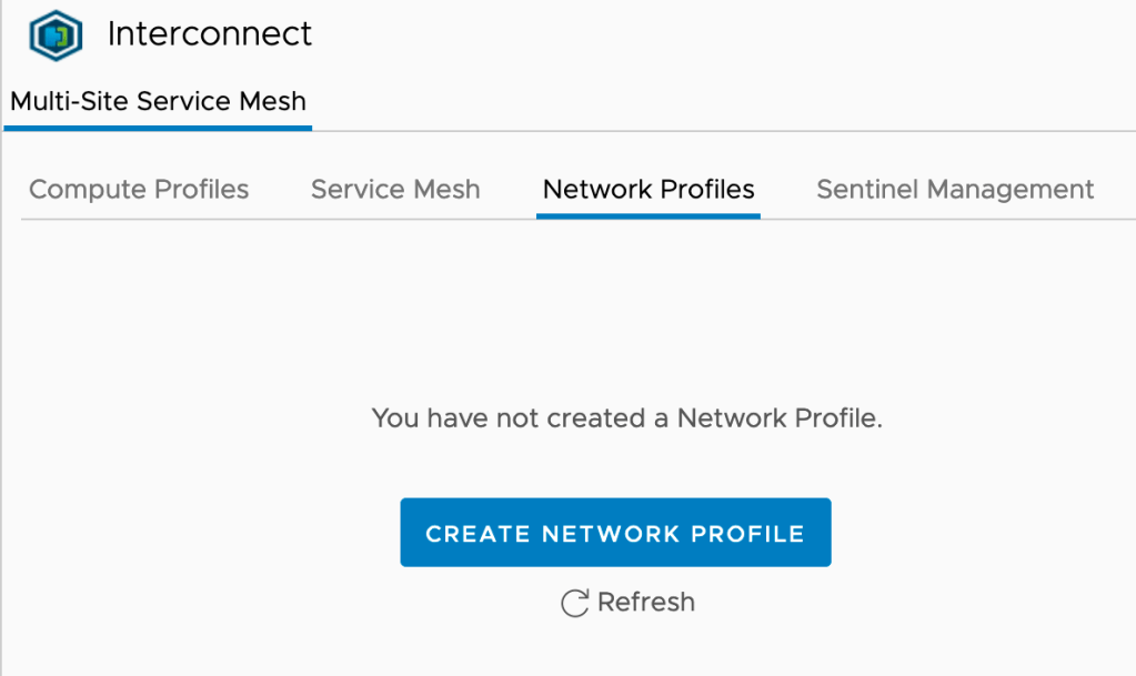
For our particular scenario we’ll create two network profiles within each site’s HCX Interconnect: One for Management and one for vMotion. In the HCX Manager UI we navigate to Infrastructure > Interconnect > Network Profiles. Click the Create Network Profile button:
The Management Network Profile for Stockholm looks as follows:

Most of the configuration details of this network profile will be self-explanatory. Notice that the Management IP pool contains two available IP addresses which is the required number for this scenario: One management IP address for the IX (Interconnect) appliance and one for the NE (Network Extension) appliance:

The vMotion Network Profile for Stockholm looks like this:

One IP address for vMotion is sufficient. We adjust the MTU to the maximum size supported by the physical network (9000 bytes in this case).
Both network profiles are now in place in Stockholm:

We create similar HCX Network Profiles in Copenhagen. The process is identical apart from different IP addresses.
Compute Profiles
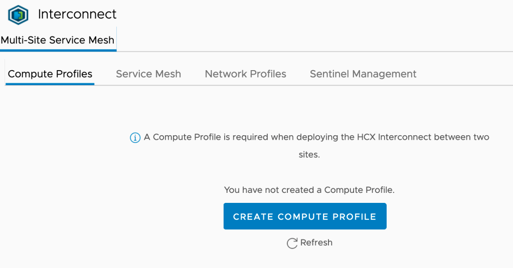
Next up are the HCX Compute Profiles. Compute profiles contain the compute, storage, and network settings that HCX will use on a site to deploy the Interconnect appliance. In the HCX Manager UI we navigate to Infrastructure > Interconnect > Compute Profiles. Click the Create Compute Profile button:
A guided process helps us configure and create the compute profile. Let’s walk through the configuration for the Copenhagen compute profile
1. Name your Compute Profile
Giving it a descriptive name so that everybody understands what we’re talking about:

2. Select Services to be enabled
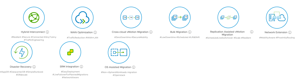
Here we select the HCX services that we want to enable in this compute profile. For our scenario we enable:
- Hybrid Interconnect
- Cross-cloud vMotion Migration
- Replication Assisted vMotion Migration
- Network Extension:

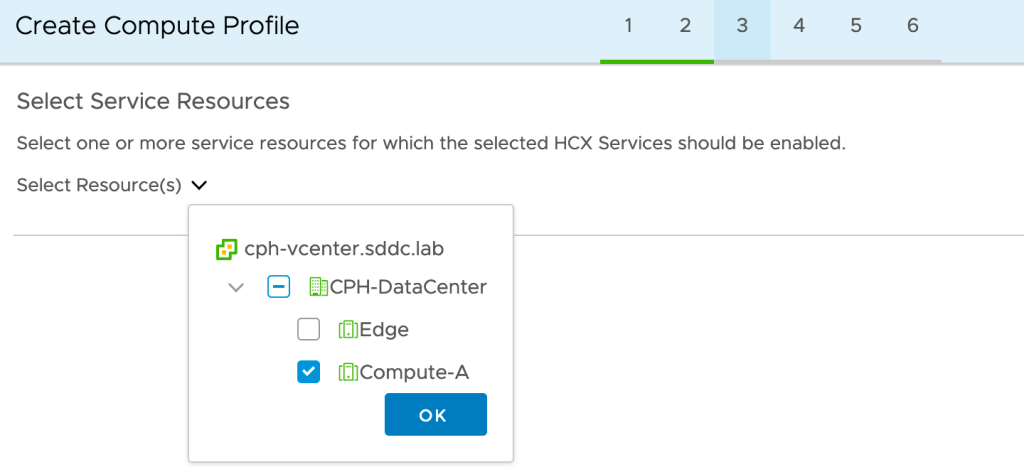
3a. Select Service Resources
We select the destination compute cluster where the migrated workloads should end up. This is a vSphere cluster called Compute-A in our destination environment:
3b. Select Deployment Resources and Reservations
In Copenhagen we want to deploy the IX and NE appliances in a separate vSphere cluster called Edge. We also need to select a datastore and can optionally choose a vCenter VM folder. We leave the reservation settings untouched.

4a. Select Management Network Profile
At this step we select the Management Network Profile that we created earlier on:

4b. Select Uplink Network Profile
In our scenario the management network will be used to reach the HCX appliances at the other site. We select the Management Network Profile as the Uplink Network Profile.

4c. Select vMotion Network Profile
At this step we select the vMotion Network Profile that we created earlier on:

4d. Select vSphere Replication Network Profile
We select our Management Network Profile as the vSphere Replication Network Profile:

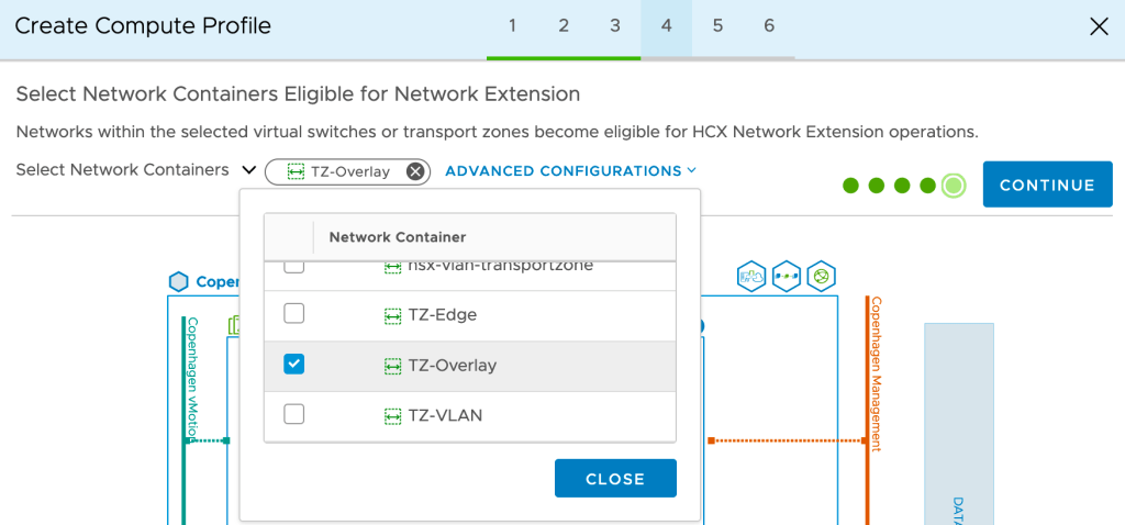
4e. Select Network Containers Eligible for Network Extension
It’s critical that we get this one right for our project. To be able to extend to overlay segments later on, we must select the NSX-T overlay transport zone here. In our case that transport zone is called TZ-Overlay:
5. Review Connection Rules
At this step we can view and copy the connections rules that HCX will created as part of the compute profile. This is particularly important information if there are firewalls between any of the different networks where HCX will have one or more endpoints.
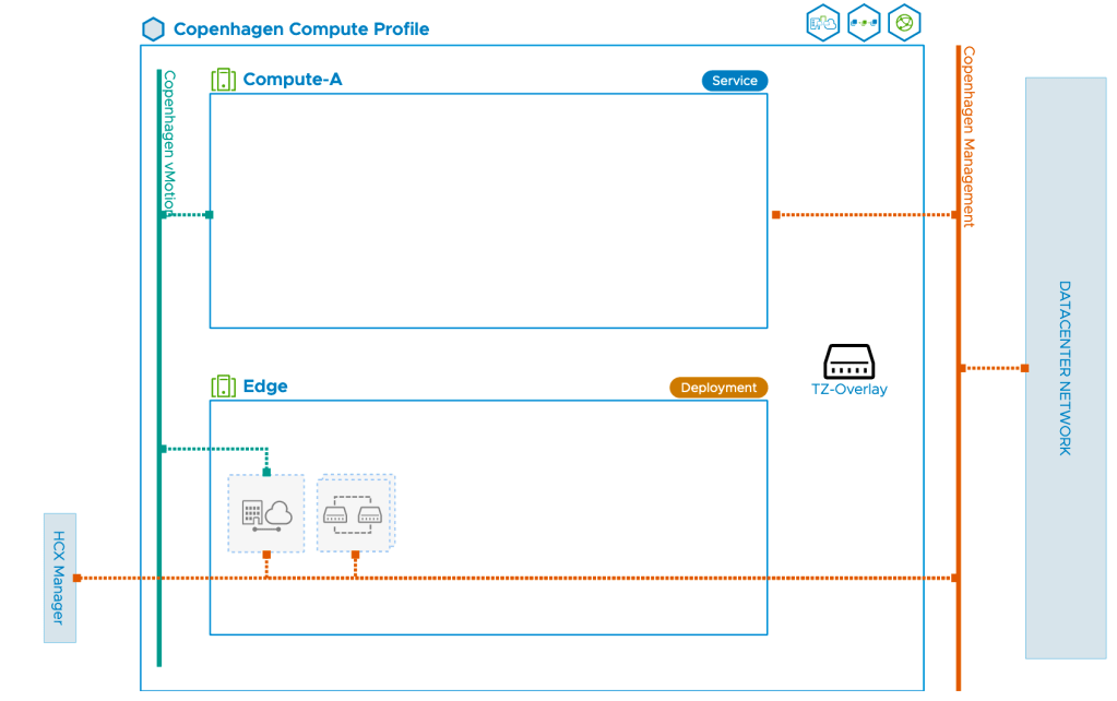
6. Ready to Complete
At the final step we’ll have a look at the diagram that gives us a nice overview of the compute profile and its components:
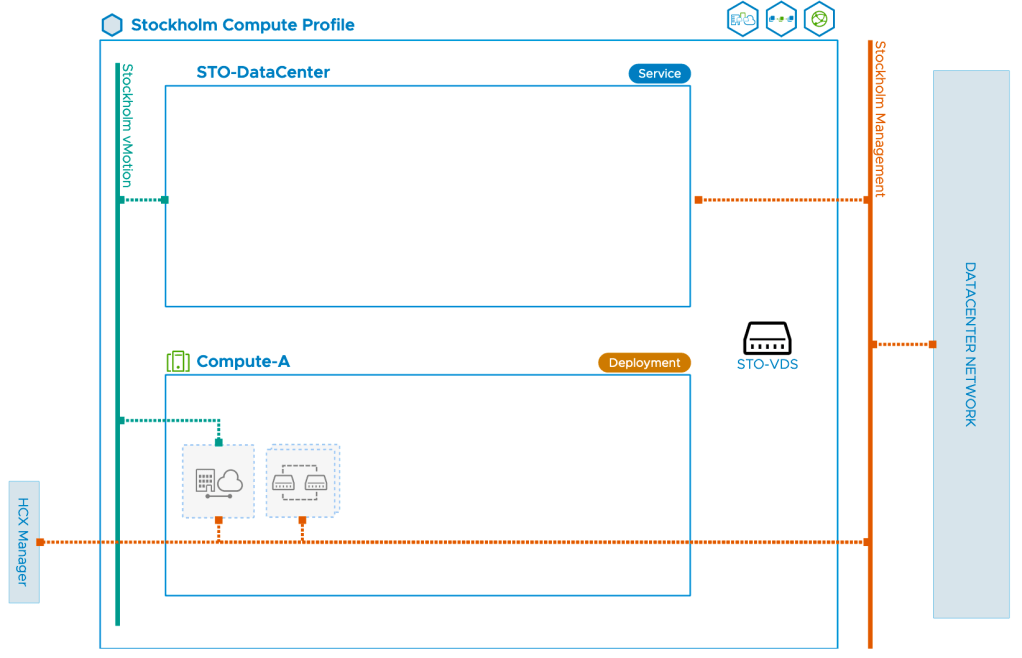
Once the compute profile in Copenhagen is created we create a similar compute profile in Stockholm. The key difference between the Copenhagen and Stockholm profiles is that in Stockholm we select the VDS for network extension. The compute profile diagram for Stockholm looks like this:
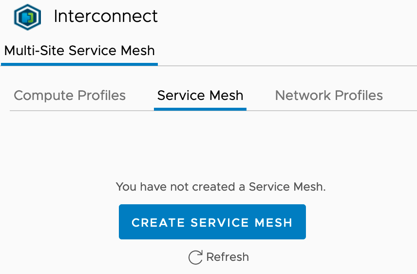
Service Mesh
The last step of configuring the HCX Interconnect is to create the Service Mesh. This is initiated from the Stockholm HCX Manager where we navigate to Infrastructure > Interconnect > Service Mesh. Click in the Create Service Mesh button:
A guided process will help us get the service mesh up and running. It’s a very straight forward process. One thing to note is that we have the option to increase the number of Network Extension appliances to be deployed as part of the Service Mesh. For our exercise one appliance will do, but it’s good to know we can scale out if necessary.
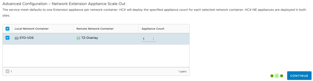
At the last step of the wizard we configure a name for the service mesh and can view another diagram showing the topology of the service mesh we’re about to deploy:

Once the service mesh is created we can see its status and properties in the HCX Manager UI:

Everything green and happy so we’ll move on.
Step 2 – Create HCX Network Extension
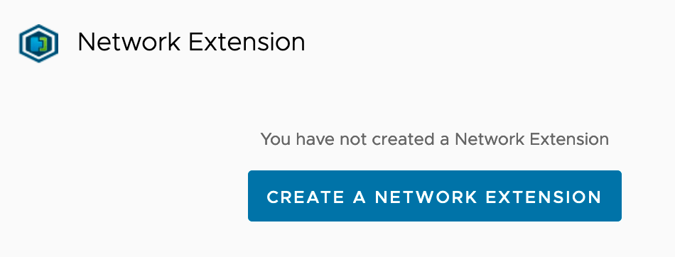
With the HCX Interconnect now fully configured and deployed we start creating the HCX Network Extensions needed for our project. Within the HCX Manager interface in Stockholm we navigate to Services > Network Extension. Click Create a Network Extension:
We are presented with a list of distributed port groups that are eligible for the network extension:
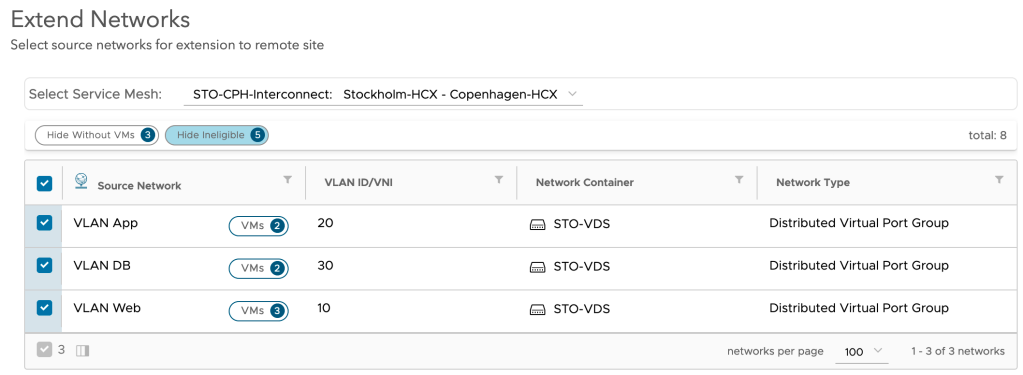
We select Stockholm’s three distributed port groups and click Next. Now things start to get interesting:

Here we basically configure the NSX-T side of the extension. We select the Tier-1 Gateway and configure a gateway IP address for the overlay segments. Note that HCX Network Extension is going to create these overlay segments for us.
Once we click Submit the network extension is created. After a minute or so we should see the following status:

So what do things look like within NSX-T in Copenhagen at this point?

Pretty much what we were hoping for (apart from the horrible segment names). HCX Network Extension has created three overlay segments connected to the Tier-1 Gateway; one for each extended distributed port group in Stockholm. We also see that the HCX network extension virtual appliance has connected itself to the segments.
A closer look at one of the created overlay segments reveals that connectivity is currently switched off.

This means that the IP subnets associated with those overlay segments are currently not advertised to any routing table. If we for example look at the routing table of Copenhagen’s Tier-0 Gateway we indeed see that it doesn’t contain routes to any of the new overlay segments (172.16.x.x):
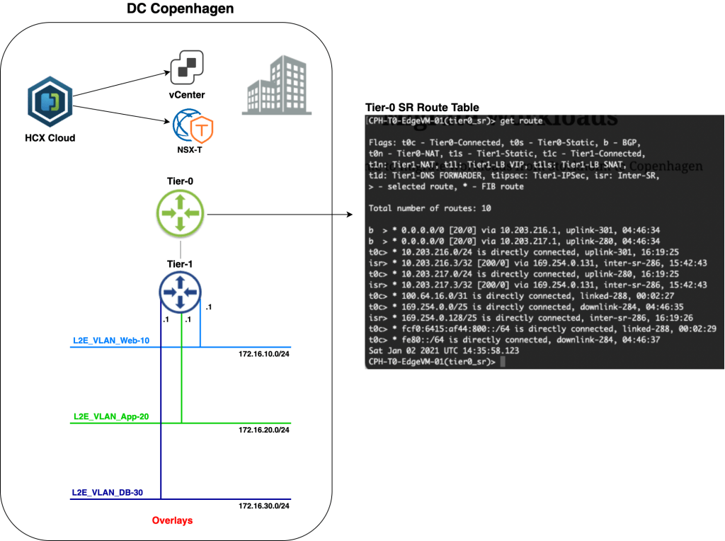
This is by design, of course. At this point the Tier-1 Gateway is not participating in any routing as we’re effectively bridging back and forward between the data centers. More on this in a moment.
Step 3 – Migrate Workloads
Finally, time to move workloads from Stockholm to Copenhagen. Migrations are managed in the HCX Manager UI under Services > Migration. Click on Migrate to kick off the migration wizard:

We’ll start with migrating virtual machine Web01. We need to specify some details for compute and storage at the destination. As Web01 is connected to a HCX extended distributed port group, it (correctly) assumes that we want to connect the virtual machine to the corresponding overlay segment once it lands in Copenhagen:

Pressing Go starts the workload migration. Once Replication Assisted vMotion (RAV) is done with its migration magic, we’ll have the following status in the HCX Manager UI:
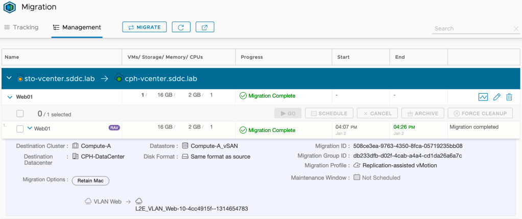
“Migration Complete”. That’s a good start I think. Let’s have a look in Copenhagen’s vCenter:

Yup, virtual machine Web01 is definitely running in Copenhagen. What do we see from an NSX-T point of view?

A virtual interface with a familiar IP address. Looking good there as well!
Seamless?
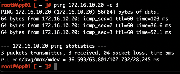
So exactly how seamless is a migration like this? This will depend on a number of things of course, but when using HCX vMotion/Replication Assisted vMotion and HCX network extension it could indeed be very close to seamless. I ran a ping during the migration of Web01 and I missed just 3 replies:
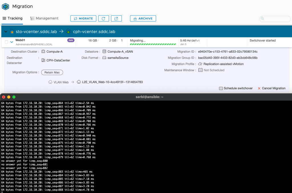
I think for most customers and scenarios this would be good enough.
Step 4 – Validate Connectivity
So, the Web01 virtual machine was migrated successfully to the Copenhagen data center. We need to have a look at its network connectivity. Before we do that, let’s check the diagram for the current situation:

A couple of things changed. We now have a fully configured HCX Interconnect and a HCX Network Extension connection. HCX NE created the required NSX-T overlay segments in Copenhagen. Virtual machine Web01 now lives in Copenhagen and is connected to an overlay segment. All looking good I believe.
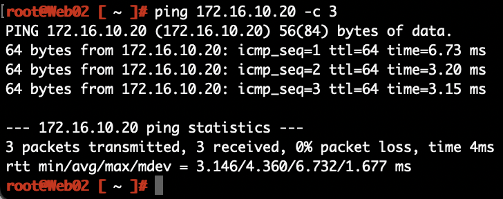
Can we ping it?
From Web02 in Stockholm to Web01 in Copenhagen:
The network path for the packets:

From Web01 in Copenhagen to DB01 in Stockholm:

The network path for those packets:

From a client in the Oslo office to Web01 in Copenhagen:
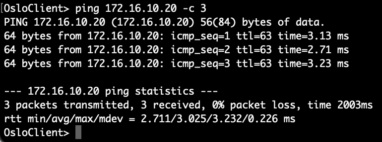
The packets from Norway to Denmark:
That all works as expected, but as you probably noticed, all routing is still done in the Stockholm DC. This becomes painfully obvious after migrating App01.
A ping from App01 in Copenhagen to Web01 in Copenhagen:
The network path:

Look at the size of that thing! This phenomenon is called traffic tromboning. It’s something you easily end up with when messing around with bridging and routing over data center interconnects. You normally don’t want these type of network paths to stick around for too long. We’re moving workloads here which means this should be a temporary situation. When we unextend the networks, we’ll also make sure that routing takes place on the Tier-1 Gateway in Copenhagen.
Avoid Trombones?
When using HCX Network Extension to extend networks from a data center environment to a VMware Cloud on AWS SDDC environment, you have the option to enable HCX Mobility Optimized Networking. MON provides routing based on the locality of the source and destination virtual machines. The MON feature hasn’t made its way to HCX Network Extension between data centers yet, but is available for early adoption and can be requested from VMware. This might be something to consider if your network extensions are going to be around for a longer period of time.
Step 5 – Unextend Networks
We’ve successfully migrated all workloads from Stockholm to Copenhagen. Connectivity is good, but it’s really time to get rid of those traffic trombones. Two important things to keep in mind before unextending a network:
- The extended network at the source (VLAN in Stockholm in our scenario) should be vacated and ready to be shut down.
- Enable connectivity on the overlay segment at the destination (Copenhagen in our scenario).
Unextending a HCX extended network is simple and done from the HCX Manager UI under Services > Network Extension. Here we click the three vertically aligned dots and chose Unextend Network:

As mentioned, once the network is unextended we need to shut down the VLAN IP interface in Stockholm and enable connectivity on the overlay segment in Copenhagen.
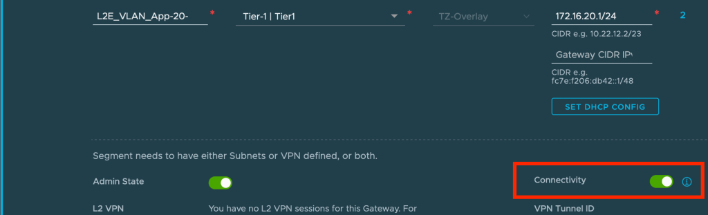
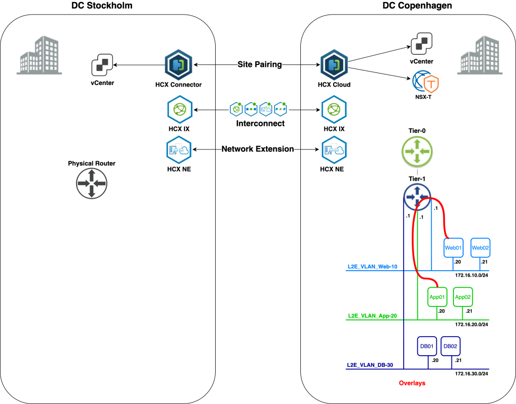
From now on the Tier-1 Gateway will handle routing traffic for this segment. We repeat the unextend process for the other extended networks and after that we’re enjoying an optimal network traffic path:
From Web01 in Copenhagen to App01 in Copenhagen:

An optimized network path:
In real life we would probably want to automate the whole unextending process including shutting down VLANs and enabling segment connectivity to keep the impact to a minimum.
Mission Completed
Seamless migration of workloads from Stockholm to Copenhagen and from VLAN to NSX-T overlay. We did it!

Yes, I renamed the overlay segments to something more user friendly 😉
Summary
Quite a battle, but it was worth it, right?
In this post we walked through setting up HCX network extensions between VLANs in one data center and overlay segments in another. This is yet another way to migrate workloads to NSX-T overlay without downtime. So, what does HCX bring to the table that the NSX-T native network extension methods do not? Well, if you read this post I think it’s quite obvious. HCX takes care of all aspects surrounding workload migrations. Not only does it handle bridging of networks between different environments, it also orchestrates and carries out the migrations in an intelligent way.
Thanks for reading.
References and resources:

Leave a comment