In the previous article we had a look at how VLAN-connected workloads were migrated to NSX-T overlay by setting up a bridge between VLANs and NSX-T overlay segments. This works well in scenarios where layer 2 adjacency between source and destination environment can be achieved. In other words, we can stretch the source VLAN(s) to the NSX-T Edge where the bridging takes place.
When source and destination environments are in completely separate environments, stretching VLANs might not be an option and thus bridging is off the table. But you still have all these workloads that need to be migrated to NSX-T overlay without re-IP and with minimum service disruption. So now what?
In this article we’re going to have a look at another method to facilitate migration of workloads from VLAN to NSX-T overlay when source and destination environment are different data centers and different administrative entities. By leveraging layer-2 VPN a customer will migrate their VLAN-connected application to a service provider’s NSX-T overlay. We have a lot to do so no time to waste!
The Environment
Let’s begin with a look at the starting point for today’s exercise:
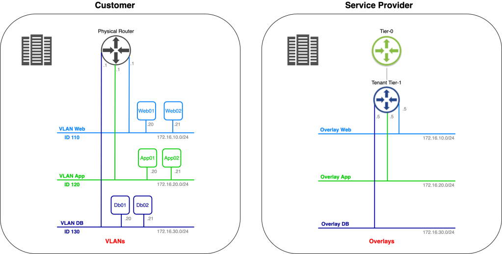
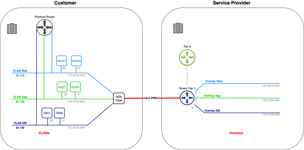
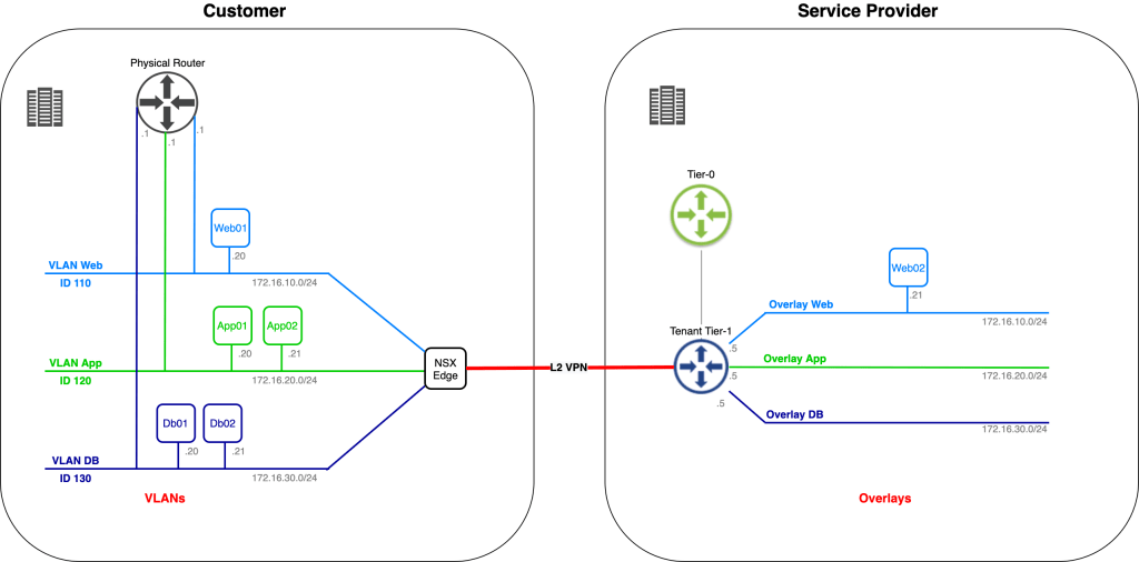
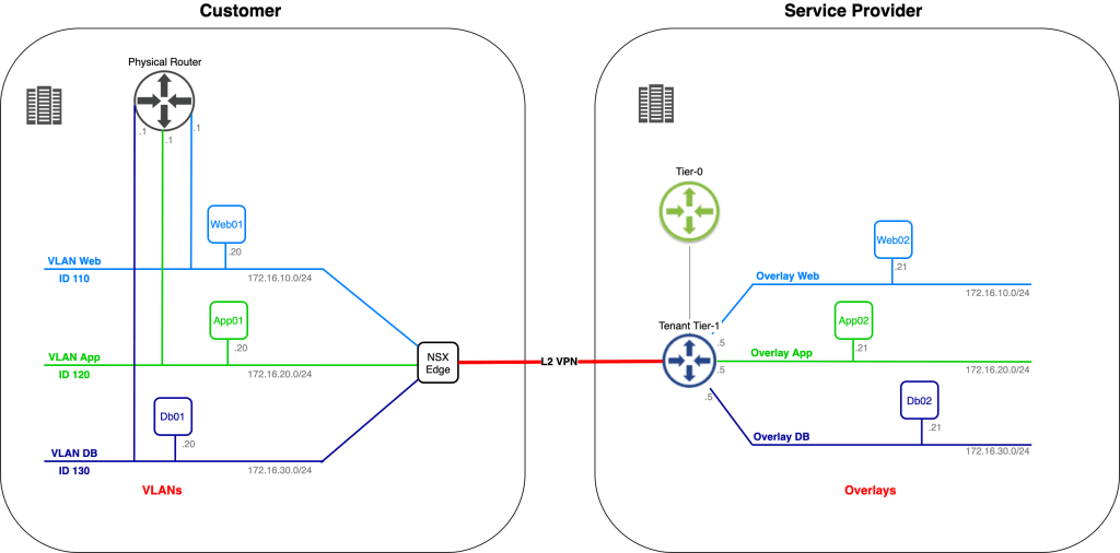
We have the customer environment on the left. One of their applications, consisting of six virtual machines, connected to three different VLANs, is to be migrated to the service provider on the right. The service provider has already prepared a spot for the customer’s application in their software-defined network.
We’re assisting the customer and service provider with phase one of the application migration. This phase consists of migrating Web02, App02, and Db02 to the service provider’s environment. IP addresses of the virtual machines must remain the same throughout the migration and inter/intra application tier communication must stay intact regardless of where a virtual machine is running (customer or service provide environment).
Mission impossible? Let’s find out!
Step 1 – Create Port Groups (Customer side)
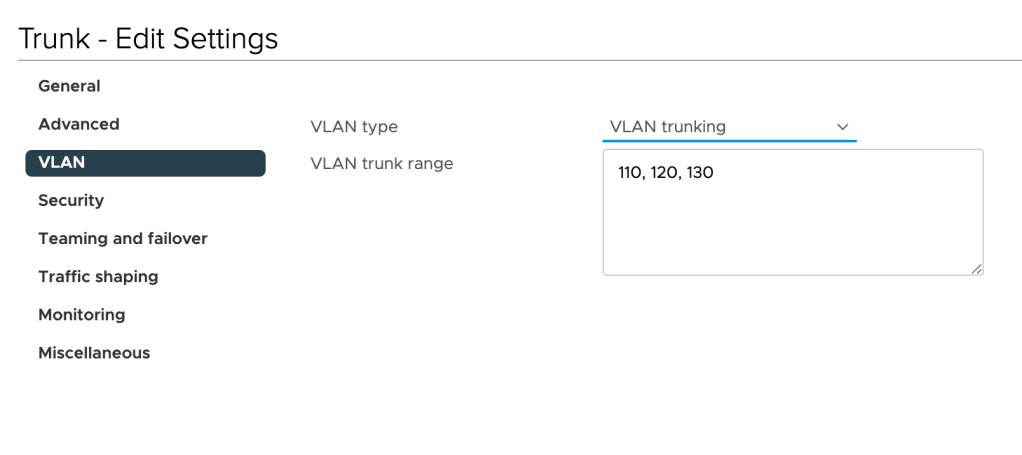
As a preparation for the next steps, we begin with creating two distributed port groups in the customer’s vSphere environment: One trunking port group and one “uplink” port group.
The “Trunk” port group is configured to carry VLANs 110 (Web), 120 (App), and 130 (DB):
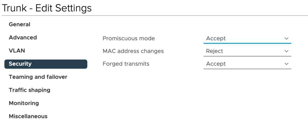
Furthermore, we need to enable Promiscuous mode and Forged transmits on this port group by setting these to Accept:
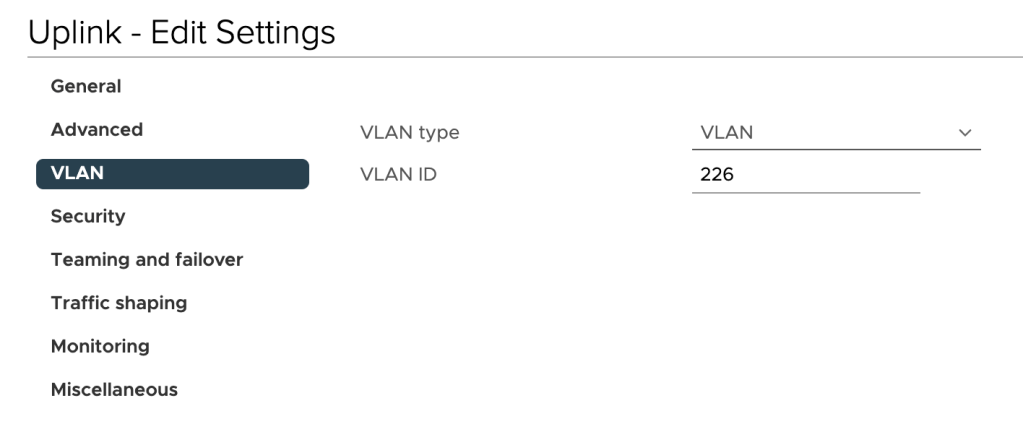
The “Uplink” port group should be mapped to a VLAN that can route traffic to the service provider’s L2 VPN endpoint. In our scenario the customer has allocated VLAN 226 for the purpose:
Step 2 – Deploy NSX Autonomous Edge (Customer side)
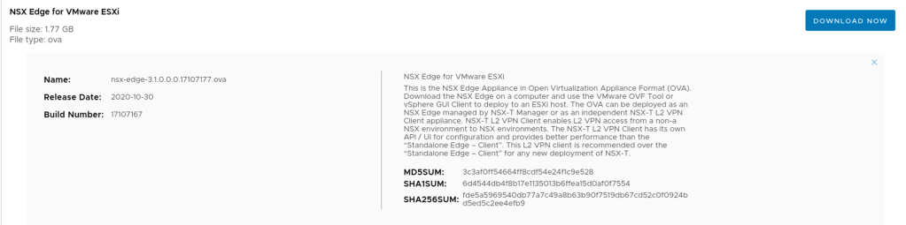
Strange enough, our customer has not implemented NSX-T in their environment. Fortunately, we can deploy a standalone NSX Edge appliance that will act as the L2 VPN client. This standalone NSX Edge appliance can be downloaded as an OVA package from VMware:
Before deploying the appliance let’s have a quick look at a diagram showing how this thing is connected to the network:
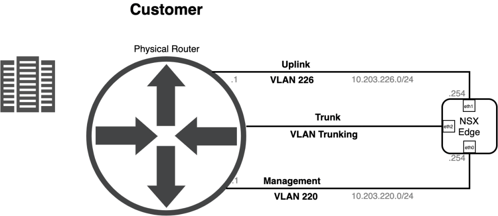
Things easily get a bit confusing during the OVA deployment so I’ve summarized the network settings for the Edge appliance OVA deployment in the table below:
| OVF Template Name | Port Group | Edge UI Name | IP Address |
|---|---|---|---|
| Network 0 | Management | Management (eth0) | 10.203.220.254/24 |
| Network 1 | Uplink | eth1 | 10.203.226.254/24 |
| Network 2 | Trunk | eth2 | – |
| Network 3 | – (HA, not used here) | eth3 | – |
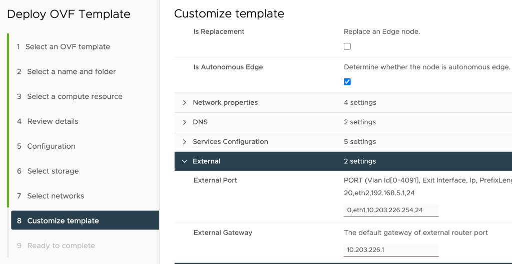
The following settings are configured at the “Customize template” step during the appliance OVA deployment:
| Setting | Value |
|---|---|
| Is Autonomous Edge | Yes |
| External Port | 0,eth1,10.203.226.254,24 |
| External Gateway | 10.203.226.1 |
The “0,eth1,10.203.226.254,24” string instructs the installation to configure “10.203.226.254/24” as the IP address on “eth1” (the uplink interface). The “0” indicates that the interface is connected to a port group that has a VLAN ID specified. If it were connected to a trunking port group we would have to specify the VLAN ID here instead.
The settings from the table above configured during the OVA deployment:
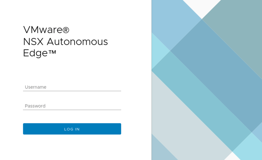
Once the NSX Edge appliance has been deployed we can navigate to the NSX Edge appliance UI on the configured management FQDN/IP address:
We’ll come back to the customer’s NSX Autonomous Edge in a bit.
Step 2 – Configure VPN Service (Service Provider side)
At the service provider side we need to configure a L2 VPN Server Session. This is achieved by completing a couple of steps which I’ll walk through here.
Add IPSec Service
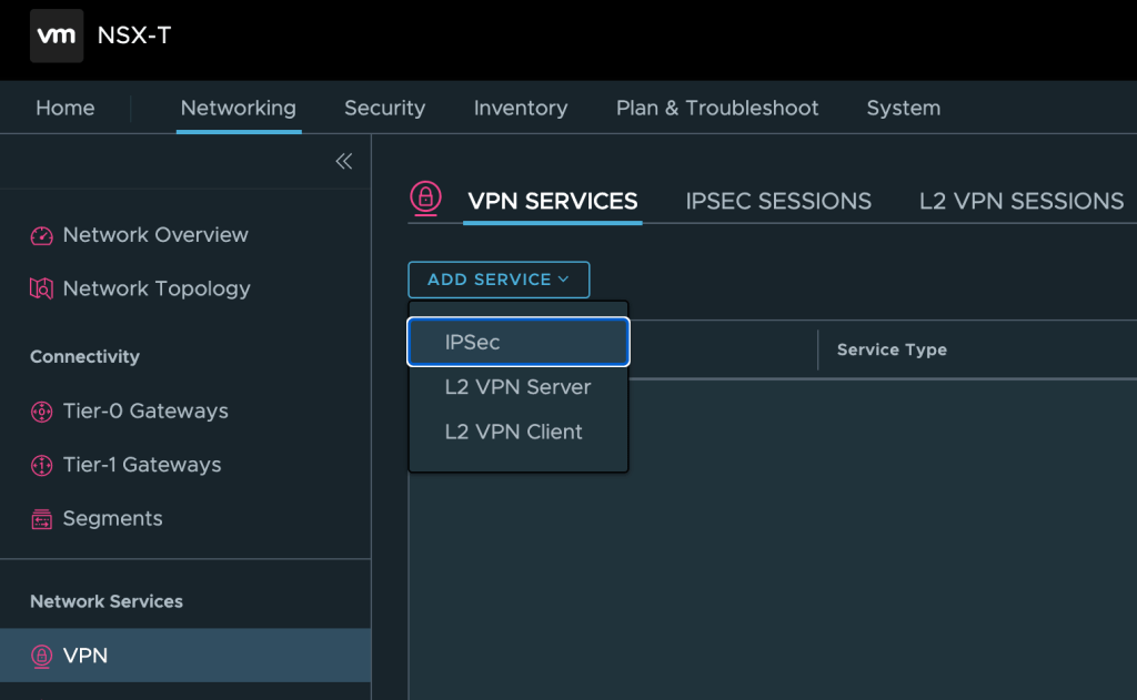
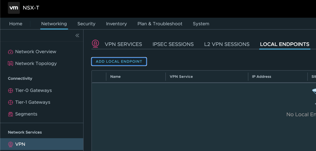
First we need to add an IPSec Service, which is the underlying protocol for the L2 VPN connection. IPSec services can be managed from the NSX Manager UI under Networking > Network Services > VPN. Here we click on Add Service > IPSec:
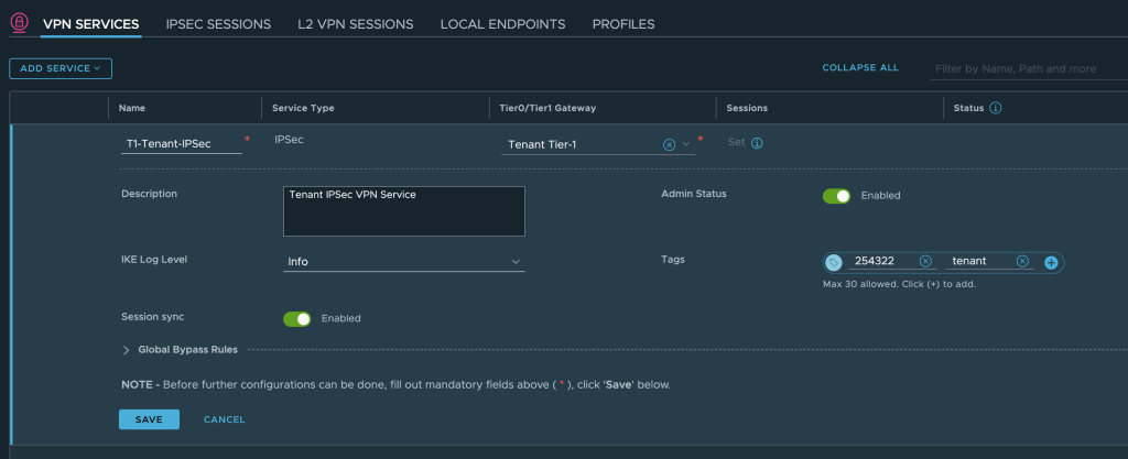
We enter a name, select the customer’s Tier-1 Gateway (which was already created), and save the configuration:
Add L2 VPN Server
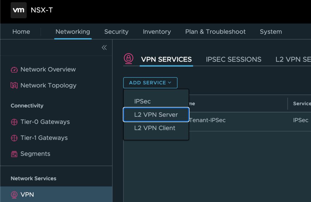
Next we need to add an L2 VPN Server. We click on Add Service > L2 VPN Server:
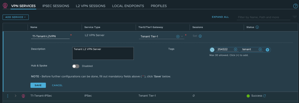
Enter a name, select the customer’s Tier-1 Gateway, and save the configuration:
Configure VPN Endpoint
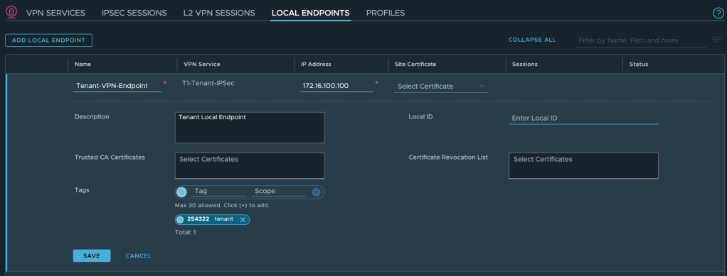
A local VPN endpoint is required and must be advertised throughout the network. Click on Local Endpoints > Add Local Endpoint:
Enter a name, select the IPSec VPN service we just created, enter a valid IPv4 IP address, and save the configuration:
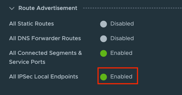
To advertise this local VPN endpoint throughout the network, we enable a Route Advertisement on the customer’s Tier-1 Gateway:
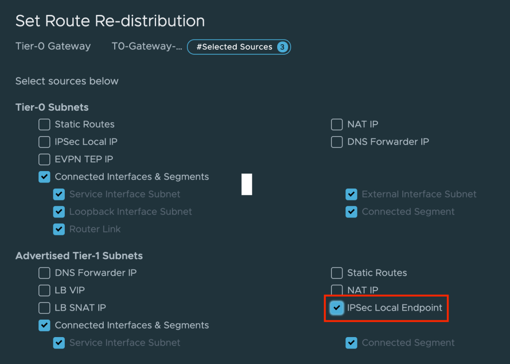
On the service provider’s Tier-0 Gateway we enable re-distribution of Tier-1 Gateway IPSec Local Endpoints:
Configure L2VPN Server Session
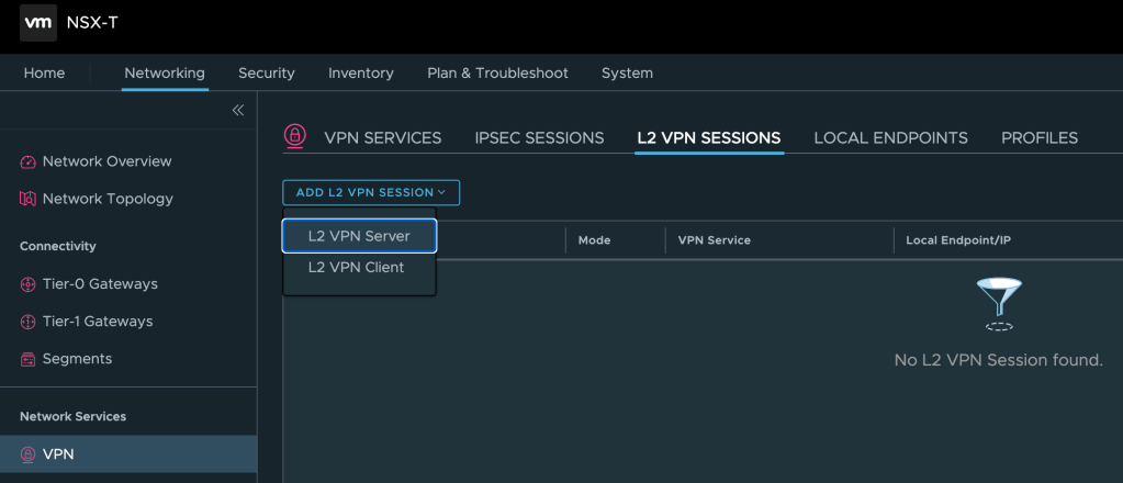
We can now configure the L2 VPN Server Session itself. L2 VPN Server sessions are managed under L2 VPN Sessions. Click on Add L2 VPN Session > L2 VPN Server:
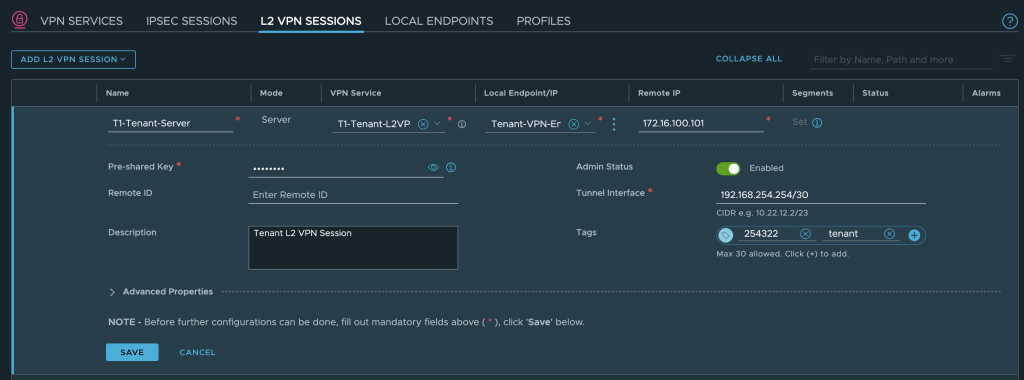
We enter a name, select the L2 VPN service, and the local endpoint. We must also specify the remote IP address which is the IP address that we configured on the uplink interface of the customer’s NSX Autonomous Edge (10.203.226.254). A valid CIDR for the tunnel interface is required as well:
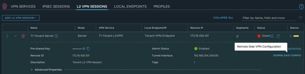
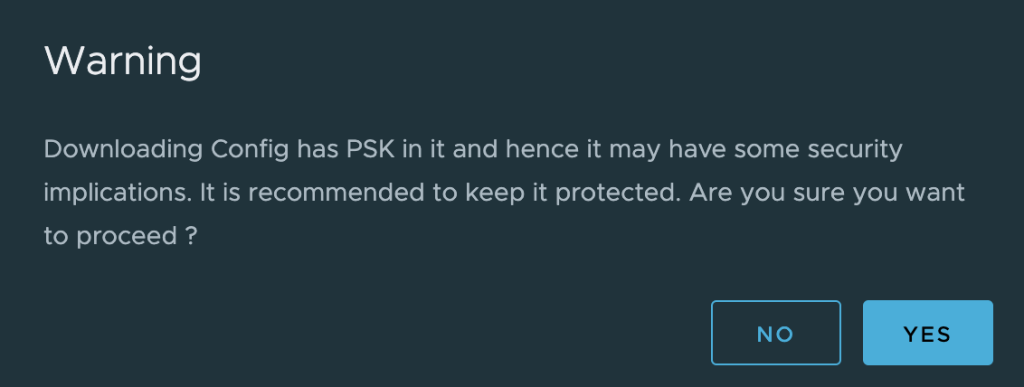
Once the L2 VPN session has been saved we can download the remote side VPN configuration which is needed on the NSX Autonomous Edge in the customer environment:
Save the configuration file to your workstation somewhere:
Step 3 – Configure L2 VPN Client (Customer side)
Now that the service provider has prepared the customer’s Tier-1 Gateway we head over to the customer environment and their NSX Autonomous Edge.
Add L2 VPN Session
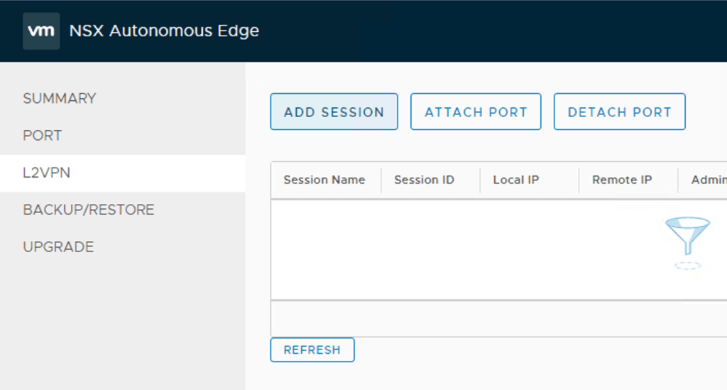
After logging in to the NSX Autonomous Edge UI we click L2VPN > Add Session
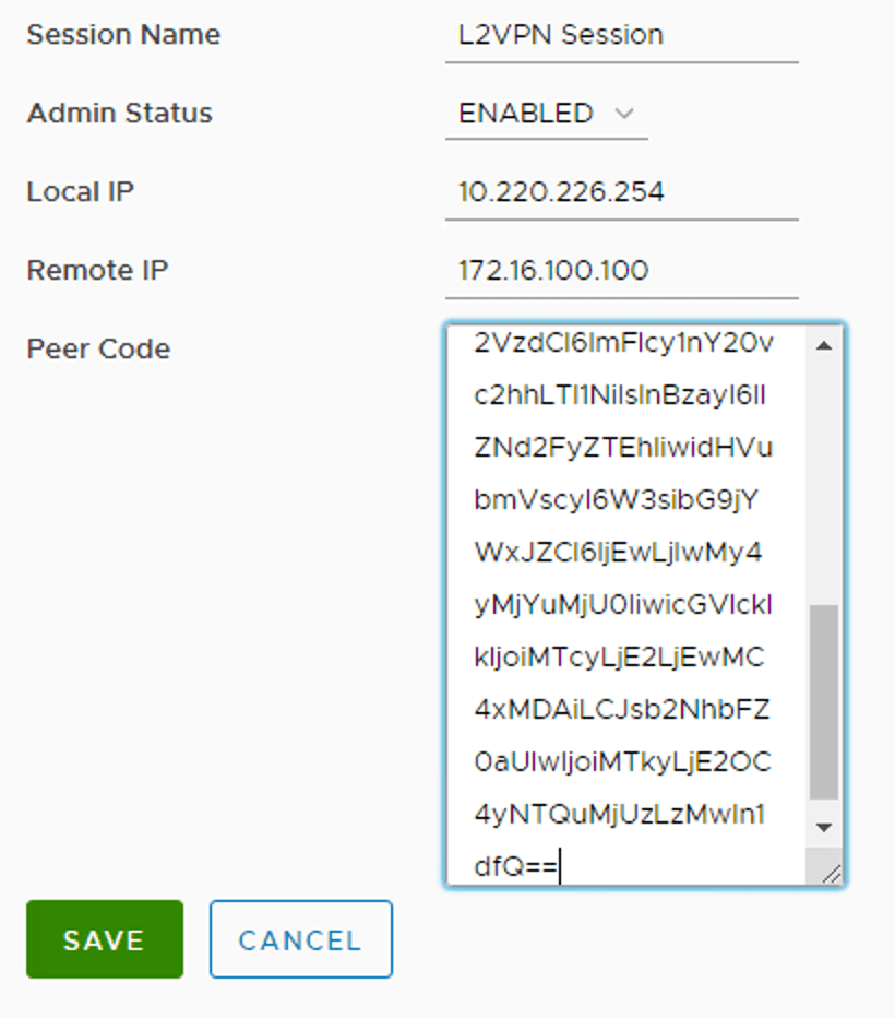
We enter the following details for the L2 VPN session:
| Setting | Value |
|---|---|
| Session Name | L2VPN Session |
| Admin Status | Enabled |
| Local IP | 10.203.226.254 |
| Remote IP | 172.16.100.100 |
| Peer Code | Peer code from the VPN configuration file |
The settings as seen in the UI:
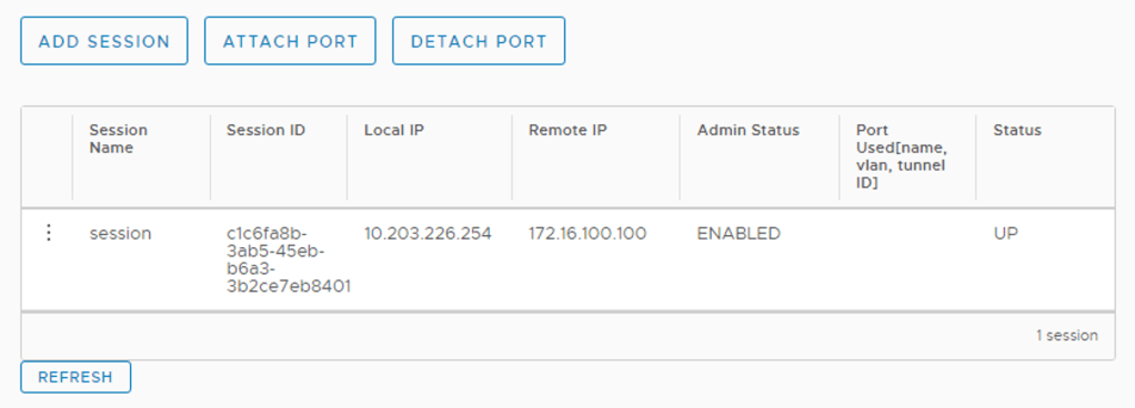
After saving the session configuration we should see the L2 VPN session with a “Up” status.
Extend VLANs
Time to extend the customer’s VLANs into the L2 VPN tunnel. In the NSX Autonomous Edge UI click on Port > Add Port
We enter the following details for each of the VLAN extensions:
| Setting | VLAN 110 | VLAN 120 | VLAN 130 |
|---|---|---|---|
| Port Name | VLAN110 | VLAN120 | VLAN130 |
| Subnet | – | – | – |
| VLAN | 110 | 120 | 130 |
| Exit Interface | eth2 | eth2 | eth2 |
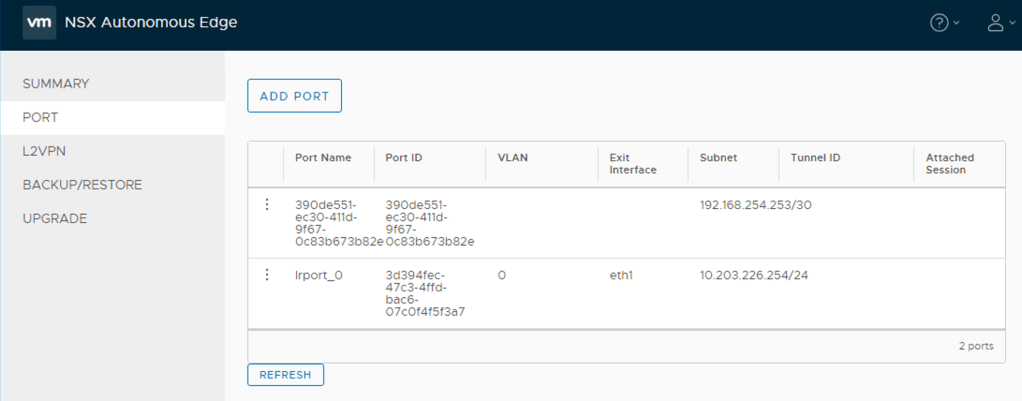
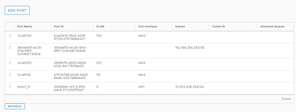
The NSX Edge UI once the ports have been added:
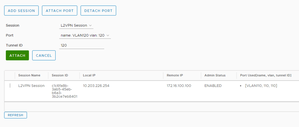
The last step is to attach these ports to the L2 VPN session. Click L2VPN > Attach Port. We select the session, the port, and configure a Tunnel ID that matches the VLAN ID. Click Save.
We’ve now effectively extended these VLANs over the L2 VPN tunnel.
Step 4 – Extend Overlay Segments (Service Provider side)
Now that the customer’s VLANs have been extended we need to do the same for the overlay segments over at the service provider.
In the NSX Manager UI navigate to Networking > Connectivity > Segments. Modify each of the customer’s segments as follows:
| Setting | Overlay Web | Overlay App | Overlay DB |
|---|---|---|---|
| L2 VPN | T1-Tenant-Server | T1-Tenant-Server | T1-Tenant-Server |
| VPN Tunnel ID | 110 | 120 | 130 |
The settings for the “Overlay Web” segment

Step 5 – Test Connectivity
Now is a good time to check if all our hard work has actually resulted in something. Let’s first have a look at an updated diagram of the environment to see where we stand from a logical point of view:
All that hard work for just a tiny red line!? Ok, let’s do a simple ping test from Web01 (172.16.10.20) to the Tier-1 Gateway downlink interface for “Overlay Web” (172.16.10.5):
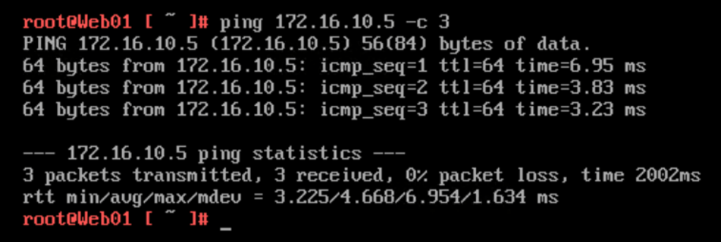
It works!
Step 6 – Workload Migration
The time has come to stretch apart the customer’s application. “Web02” is migrated to the service provider environment while “Web01” is staying behind in the customer’s environment (for now).
The workload migration itself can be done in a number of ways (OVF export/import worked pretty well in my lab ;-). But let’s assume that this has been taken care of and that we’re now finding ourselves in the following situation:
Let’s have a look at the connectivity by running a ping from “Web01” (172.16.10.20) in the customer’s environment to “Web02” (172.16.10.21) in the service provider’s environment.
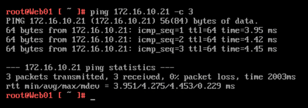
Works like charm! Pinging the VLAN 110 interface (172.16.10.1) and the Tier-1 Overlay Web downlink interface (172.16.10.5) from “Web02” (172.16.10.21):
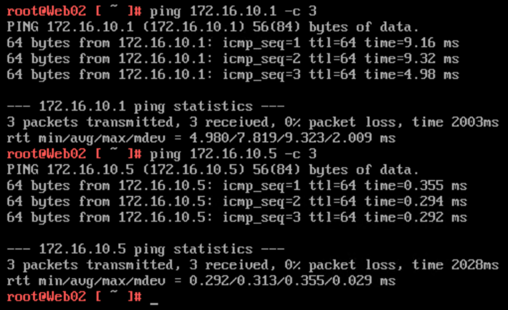
Only the difference in RTT reveals that there’s something going on between these two IP addresses. Something like a L2 VPN connection 😉
After this initial success, the customer decided to migrate “App02” to the service provider as well:

With 33% of the application now on the service provider side, we better make sure that inter-tier connectivity is still working. A ping from “Web01” (172.16.10.20) to “App02” (172.16.20.21):
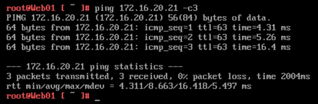
No issues here.
Things going better than expected, the customer wants to complete phase one of the migration project and migrates “Db02” to the service provider as well:
Pinging the VLAN 120 interface (172.16.20.1) in the customer environment from the newly migrated “Db02” (172.16.30.21) virtual machine:
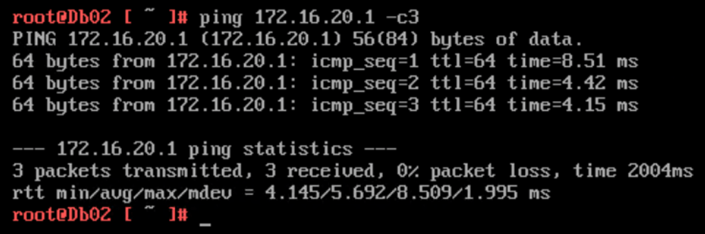
Phase one completed!
Once phase two is completed, we would un-extend the VLANs and change IP address on the customer’s Tier-1 Gateway downlink interfaces from .5 to .1. All workloads migrated without touching their OS.
Summary
In this article we had a look at how to migrate VLAN-connected workloads to an NSX overlay located in a completely separate environment. In a scenario like this, where bridging is not an option, we leverage L2 VPN to extend VLANs to NSX-T overlay.
Hopefully you found reading this post worth your time. Thank you!
References and resources:
- NSX-T Documentation
- NSX-T Livefire: Next Generation Cloud Networking
- SDDC.Lab – Automated deployment of vSphere / NSX-T labs

Leave a comment