Organizations implementing NSX-T overlay have several options when it comes to migrating existing VLAN-connected workloads to NSX-T overlay segments.
Common methods include re-IP’ing or re-deploying workloads to a new IP space allocated to NSX-T logical networking. It gives the workload somewhat of a fresh start. Besides, a re-IP process can be a very useful exercise eliminating those (hardcoded) IP address dependencies within an application.
There are however situations where neither re-IP nor re-deploy are alternatives. The reasons for this will vary, but it often has something to do with time, complexity, and cost. In those situations the workload will have to be migrated as is. Is this possible? How is it done?
In today’s article I’m going to walk through setting up a bridge between some VLANs and NSX-T overlay segments. It’s this NSX-T construct that makes it possible to migrate workloads from VLANs to overlay without having to make any changes to the workloads themselves. Let’s get started!
The Environment
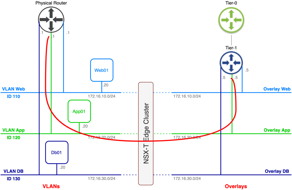
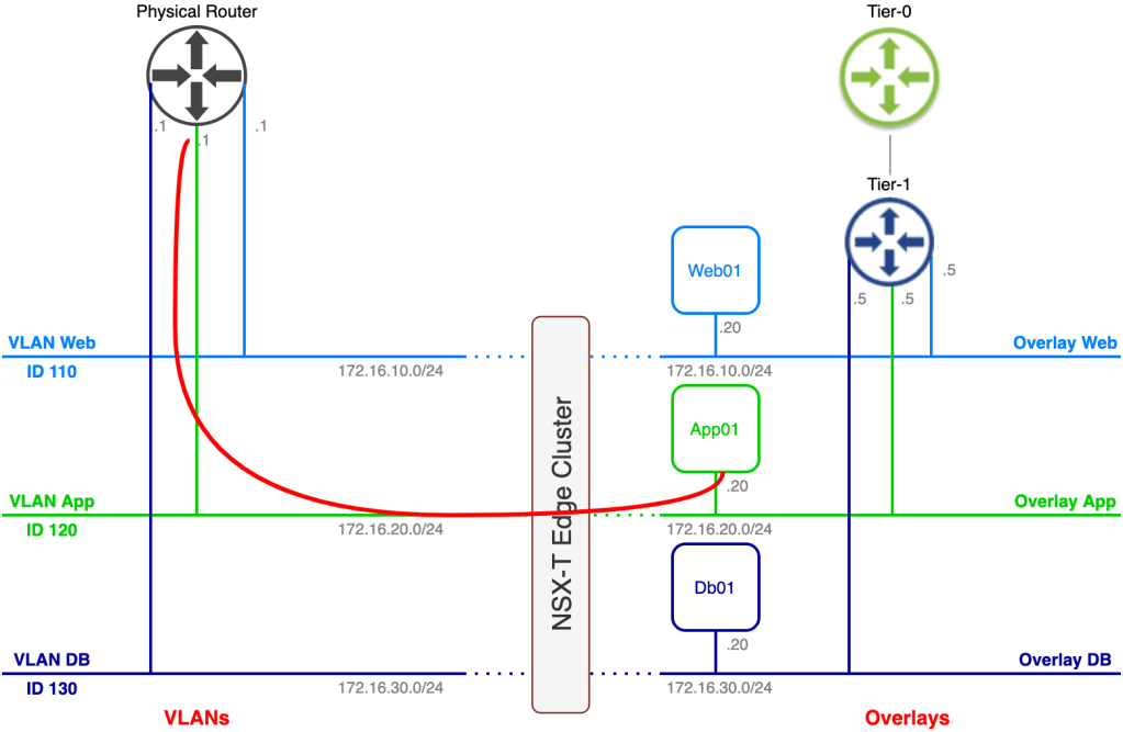
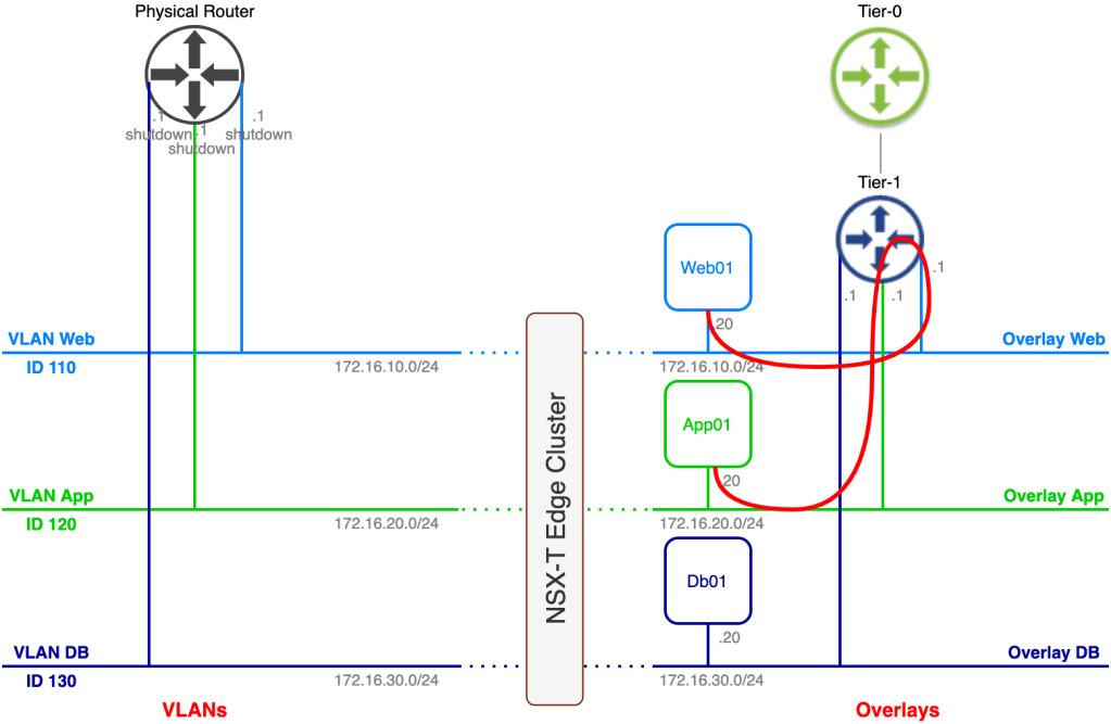
The current state of today’s lab environment from an application/network point of view looks something like this:
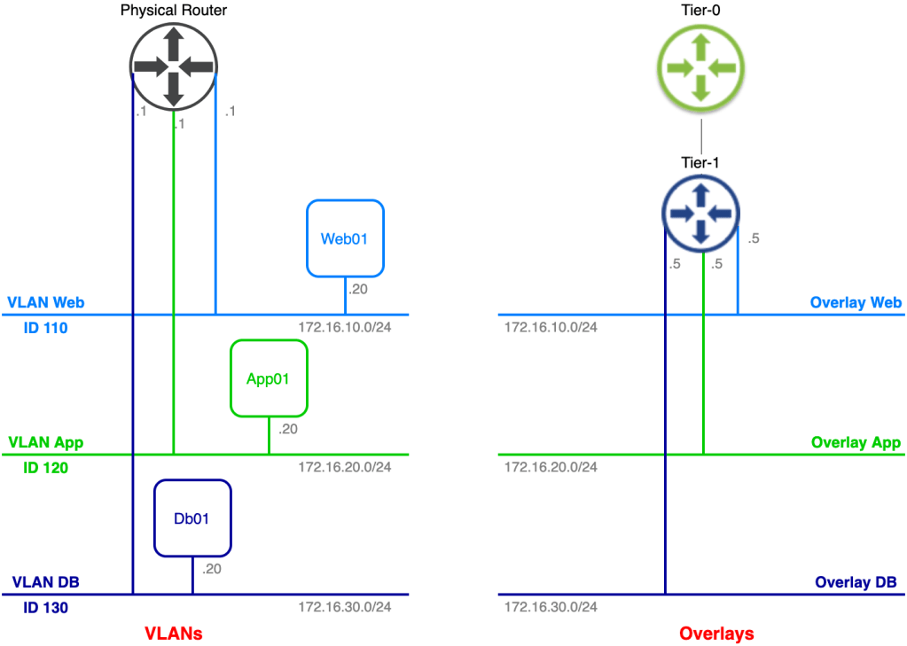
On the left side we have the legacy VLAN-based networks where a three tier application is connected. On the right side we have the NSX-T based overlay networks. Our task is to migrate the application to the NSX-T overlay without making any configuration changes to the application’s three virtual machines.
As you probably noticed some preparations have been made in advance. A Tier-1 gateway and three connected overlay segments have been created. The overlay segments match the VLAN structure and their respective IP subnets except for the default gateway of course.
This is a really good start, but we’re not quite there yet. Follow along as we configure the missing parts of our bridge.
Step 1 – Create Trunking Port Group
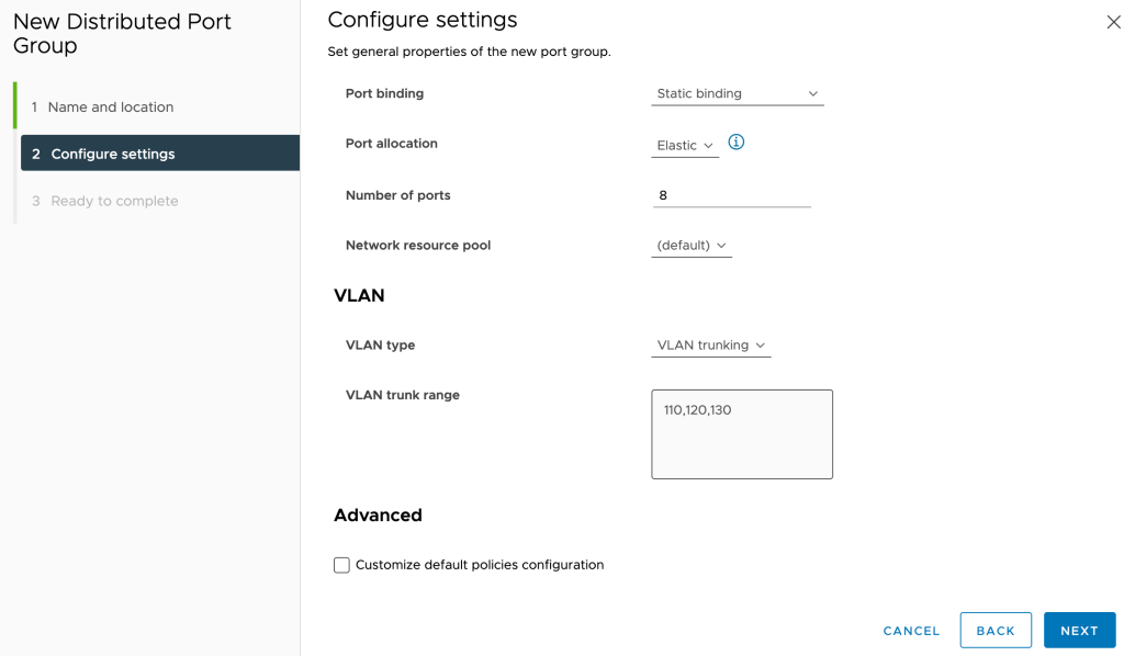
The first thing we need to do is create a port group that will carry traffic for the three VLANs that are in scope for bridging. For this scenario we create a vSphere distributed port group called “Bridge” that will be trunking VLANs 110, 120, and 130:
We need to set Promiscuous mode and Forged transmits on this port group to Accept:

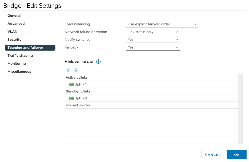
To keep things deterministic, we’ll change the Teaming and failover setting of this port group to explicit failover order with one active and one standby uplink:
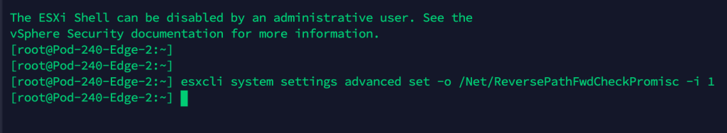
Lastly, on the ESXi hosts where the NSX-T Edge node virtual machines are running we must enable reverse filter by issuing the following esxcli command:
esxcli system settings advanced set -o /Net/ReversePathFwdCheckPromisc -i 1
After running the above command we need to disable/enable Promiscuous mode on the “Bridge” port group so that the reverse filter becomes active.
Step 2 – Create Bridge Transport Zone
Within NSX-T we create a new VLAN transport zone for bridging. Transport zones are managed under System > Configuration > Fabric > Transport Zones:
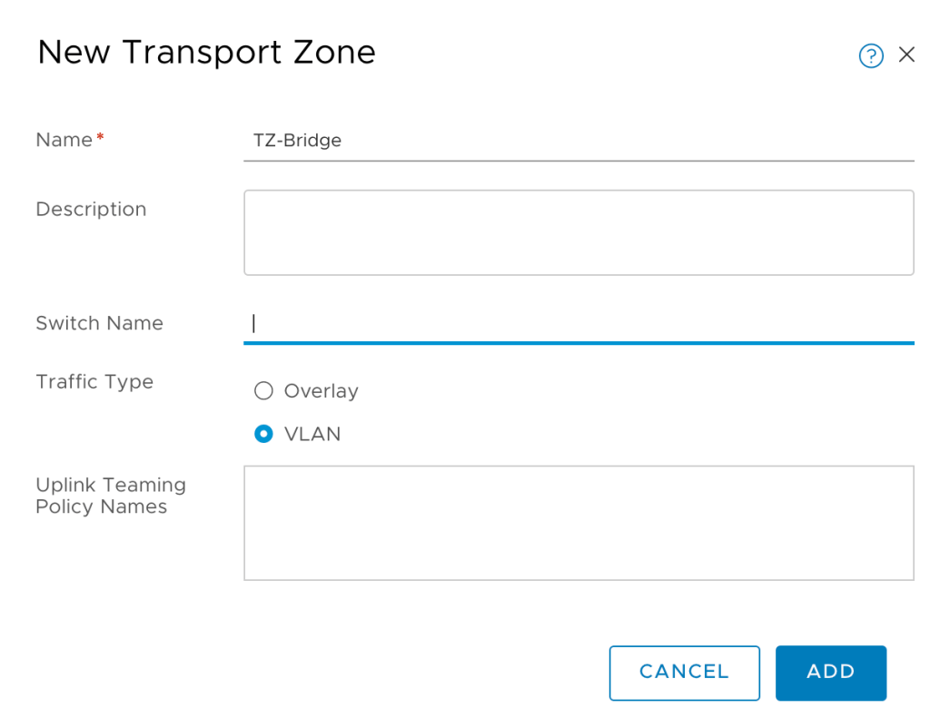
I’m calling this new transport zone “TZ-Bridge”.
Step 3 – Add TZ-Bridge to Edge Nodes
A transport zone without transport nodes isn’t much of a transport zone. Bridging in NSX-T is done via the Edge transport nodes and therefore we must add the newly created “TZ-Bridge” transport zone to the Edge transport nodes.
Edge transport nodes are managed under System > Configuration > Fabric > Nodes > Edge Transport Nodes:
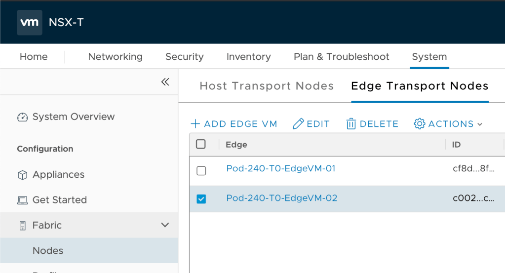
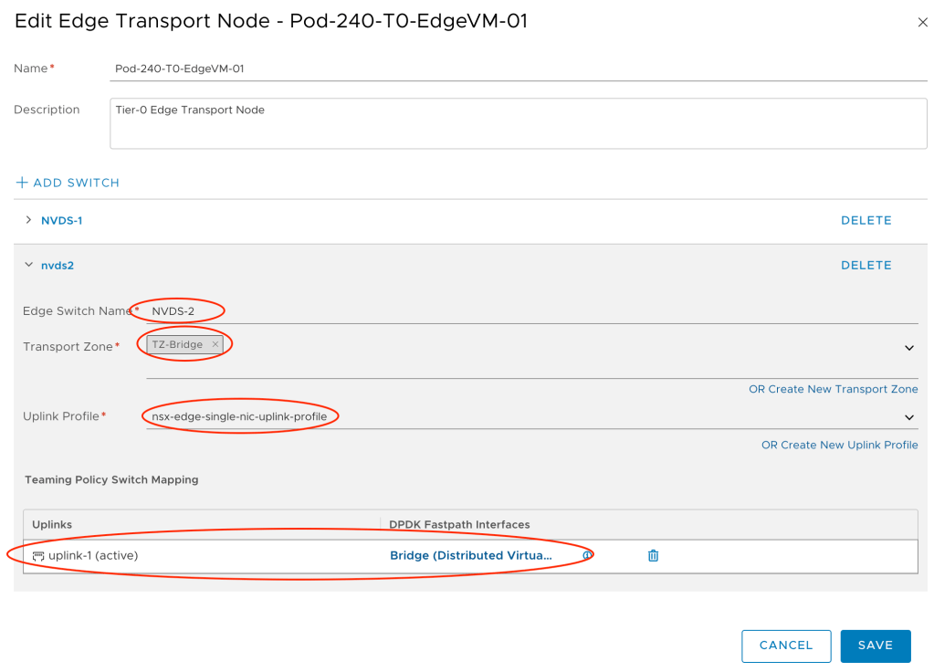
We edit each of the Edge transport nodes that will participate in bridging as follows:
- Add a new switch: Add Switch
- Switch Name: NVDS-2
- Transport Zone: TZ-Bridge
- Uplink Profile: nsx-edge-single-nic-uplink-profile
- Teaming Policy Switch Mapping: uplink-1 (active) > Bridge (Distributed Virtual Portgroup)
Step 4 – Create Edge Bridge Profile
The Edge bridge profile is the NSX-T configuration construct that ties together the Edge bridge with the overlay segments that should be part of the bridge.
Navigate to Networking > Connectivity > Segments > Edge Bridge Profiles and create a new profile with the relevant settings:
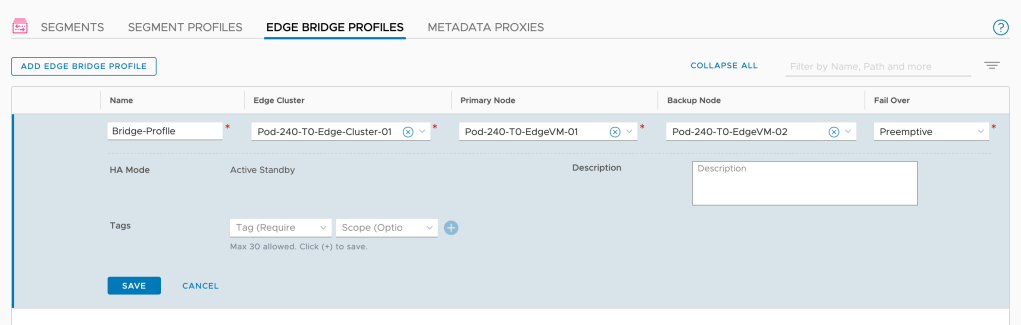
Note that you configure a primary and a backup node for the bridge.
Step 5 – Configure Bridging on the Overlay Segments
We’re getting there. The final step is to configure the overlay segments for bridging.
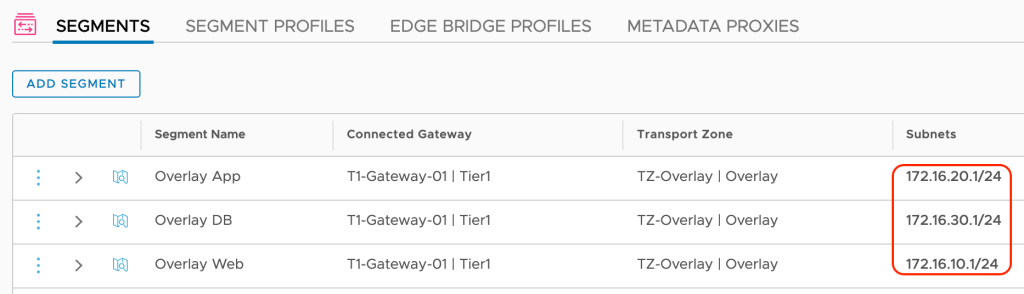
Navigate to Networking > Connectivity > Segments:
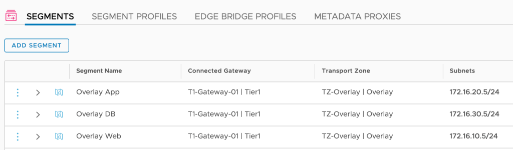
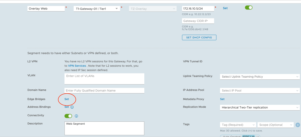
Here we modify the three overlay segments so they become part of the bridge. We begin with the “Overlay Web” segment and click the Set link for Edge Bridges:
Click on Add Edge Bridge and in the next screen select the Edge bridge profile, the bridge transport zone and the VLAN ID of the corresponding VLAN (ID 110 in this case):
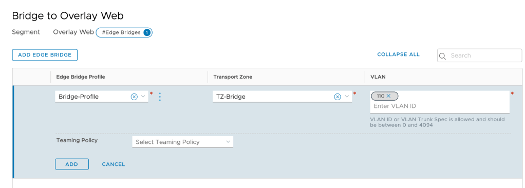
We repeat this step for the other two segments.
Verify Bridge
At this point we should have a working network bridge between the VLANs and the NSX-T overlay. To verify this we’ll perform a simple ping test from the physical router to each of the Tier-1 downlink interfaces.
We expect to receive replies from 172.16.10.5, 172.16.20.5, and 172.16.30.5:
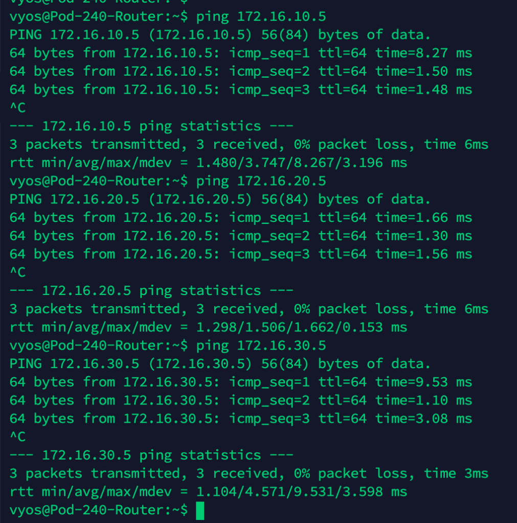
Ping replies is a good thing!
Let’s have a look at the network path for a ping from the physical router App VLAN interface (172.16.20.1) to the Tier-1 App downlink interface (172.16.20.5):
Migrate Virtual Machines
With a working bridge in place there’s nothing stopping us from migrating the VMs to the overlay segments. So let’s just do that.
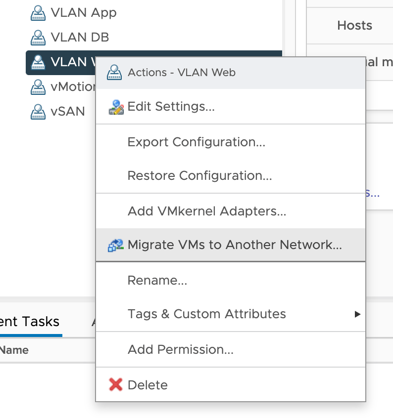
In vSphere Client, right click the VLAN port group you want to migrate from and choose Migrate VMs to Another Network:
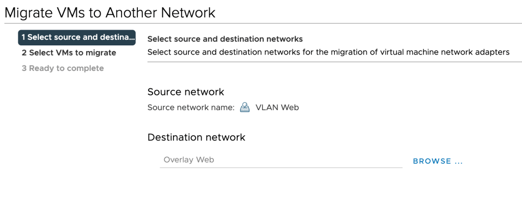
Choose the destination NSX-T overlay segment:
Select the VMs you want to migrate:
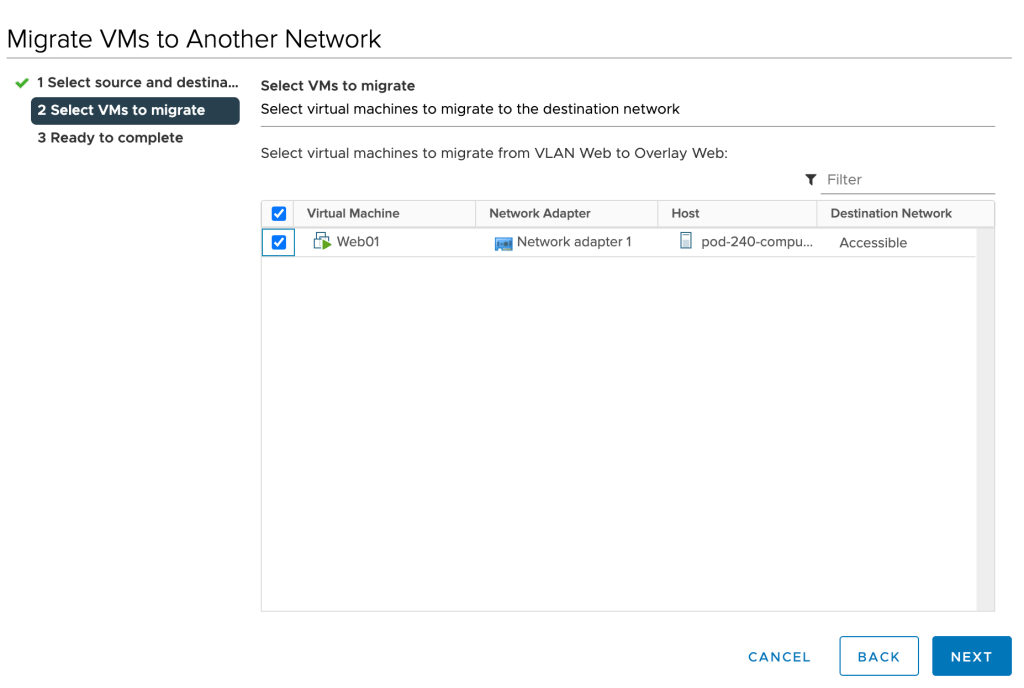
Click Next and Finish. Repeat these steps for the remaining virtual machines.
Verify Virtual Machine Networking
With the virtual machines now connected to the overlay segments, it’s probably a good time to verify that we can still reach these guys. Let’s run some pings from the physical router to the virtual machines this time:
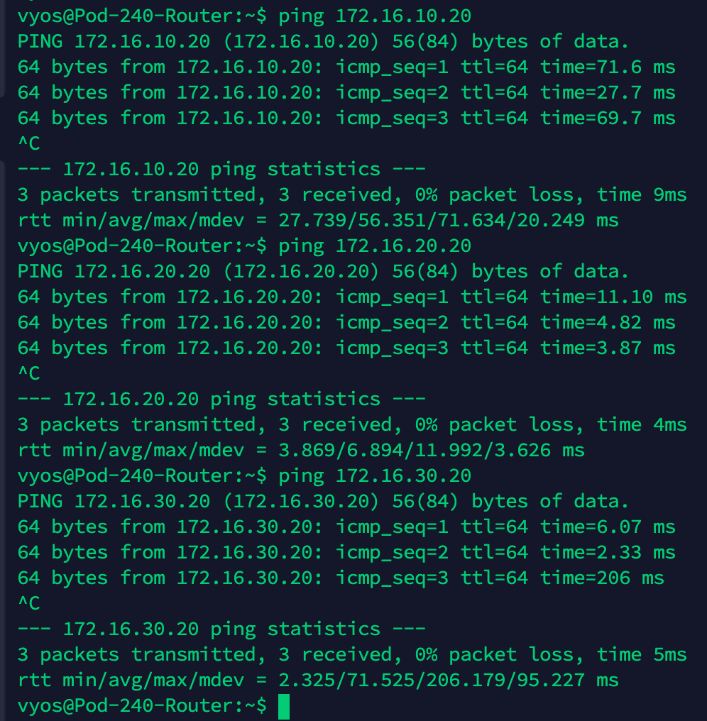
That’s seems to be working. Let’s have another look at the network path for a ping from the physical router to the App01 virtual machine:
Cool!
Optimize Network Path
While we’ve successfully migrated our virtual machines to the NSX-T overlay, we still have that nasty hairpin.
Let’s say Web01 needs to communicate with App01. With the current setup the network path for that traffic looks like this:
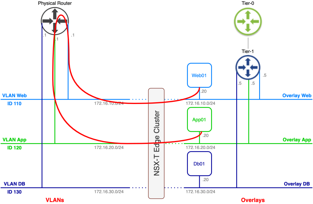
One of the reasons organizations implement NSX-T overlay is to get rid of “hairpinning” network traffic so obviously we can’t have it like this.
There are two things we can do here to mitigate the hairpin. I think that you figured it out already, but here they are:
- Migrate the default gateway from the physical router to the Tier-1 Gateway
- Change the default gateway within the VM guest OS
I personally prefer the first option. Using this option we don’t need to touch the guest OS and we also replace the physical router’s VLAN interface which is what we want to do most of the time once we emptied a VLAN.
In our scenario we weren’t allowed to change any configuration on the virtual machine which requires that we go for the first option. The process is pretty easy:
- Shut down the physical router interface that is configured with the .1 IP address
- Change the default gateway on the overlay segment from .5 to .1
After completing these steps we have achieved our goal. Using the same example as before where Web01 communicates with App01:
Much better. You might say that network traffic still hairpins through the Tier-1 gateway, and from a logical perspective it does. But the Tier-1 is a completely distributed router in this scenario (no stateful services) which means we don’t have an issue with that. With some luck Web01 and App01 are running on the same transport node and network traffic between the two never even hits the physical network.
Summary
In this article we had a closer look at configuring bridging between VLANs and the NSX-T overlay. Bridging is a useful tool in certain migration scenarios or in scenarios where layer 2 adjacency between a VM connected to the NSX-T overlay and something that isn’t is required.
Hopefully you found this post useful on your NSX journey.
Thanks for reading
References and resources:

Leave a comment