Recently a new version of the NSX-T Reference Design Guide was released. This guide, which now covers NSX-T versions 2.0 – 2.5, is a must read for anyone interested in the NSX-T solutions and their recommended design.
One of the things you’ll find in the updated guide is a new recommended deployment mode for the edge VM for NSX-T 2.5 and onwards. The new recommended design for the Edge VM looks likes this:
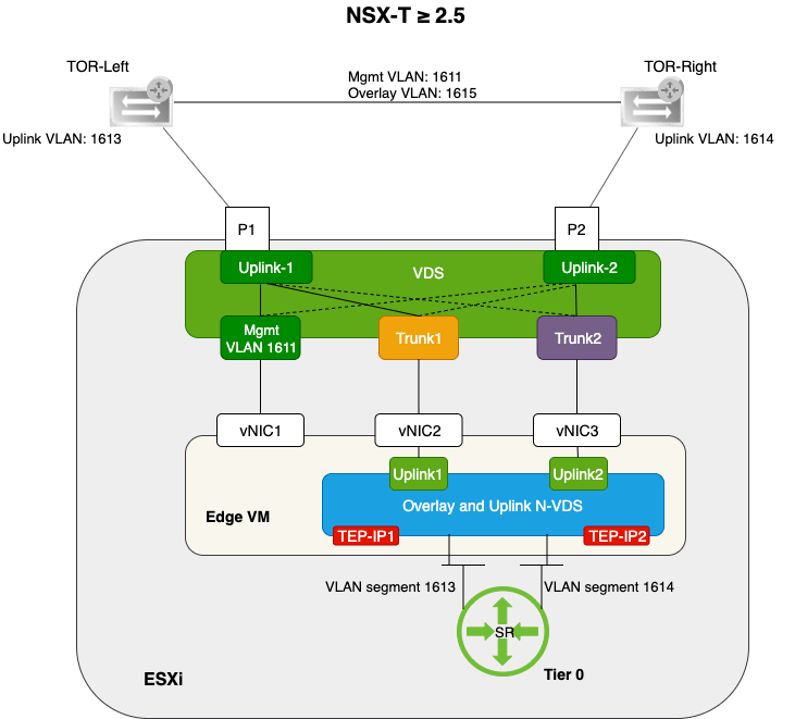
This new design has a couple of advantages:
- One N-VDS carrying both overlay and VLAN traffic.
- Multi-TEP configuration for load balancing of overlay traffic.
- Distribution of VLAN traffic to specific TORs for deterministic point-to-point routing adjacencies.
- No change required in the vSphere distributed port group configuration when new workload VLAN segments are added.
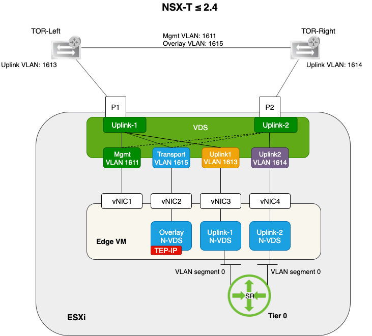
This “single N-VDS per Edge VM” design is only supported with NSX-T version 2.5 and above. For NSX-T version 2.4 and lower you stick with the “three N-VDS per Edge VM” design that looks like this:
Getting to the 2.5 Edge VM design
The “three N-VDS per Edge VM” design is still perfectly valid and fully supported with NSX-T 2.5.
Upgrading NSX-T from 2.x to 2.5 won’t touch your Edge VM configuration so you automatically end up with the “three N-VDS per Edge VM” design in version 2.5.
And in most cases there’s no immediate reason to start messing around with the Edge VM design in a production environment just to have it aligned with the recommended design for version 2.5.
That being said, I wanted to go through the process just to see if it could be done with acceptable data plane disruption and of course to learn a thing or two in the process. Maybe you want to follow along and perhaps learn something too. Let’s have a look at what I did.
Step 1 – Create VLAN trunking port groups
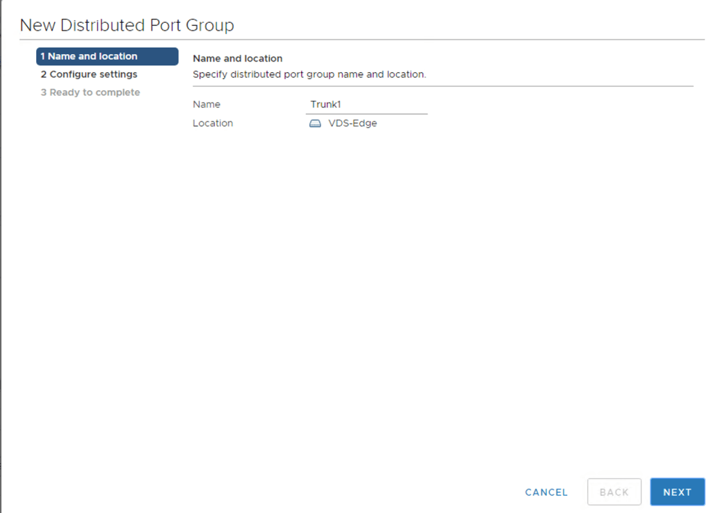
I’m using my 2.5 Edge VM design diagram above as a blueprint and the first thing that I need to do is create two new port groups on the vSphere VDS. The Edge VM design requires two port groups configured as trunks. I will call these port groups Trunk1 and Trunk2.
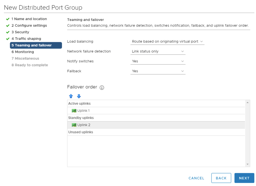
Starting with Trunk1:
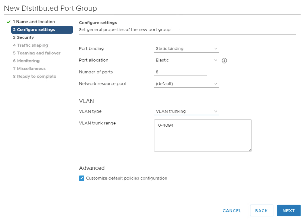
Setting the VLAN type to VLAN trunking:
For Teaming and failover I configure Uplink 1 as the active uplink and Uplink 2 as the standby uplink:
I then create the Trunk2 port group and configure it the same way except for the Failover order which is set the other way around:

The following port groups are now available on the VDS:
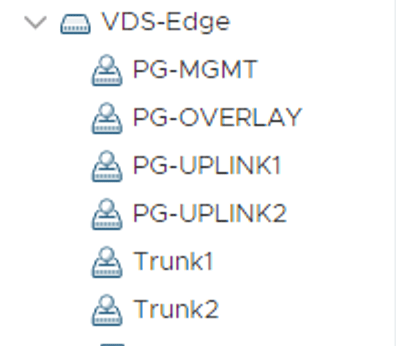
The idea here is that Trunk1 and Trunk2 will replace PG-OVERLAY, PG-UPLINK1, and PG-UPLINK2.
Step 2 – Create new Tier 0 transit segments
The current “three N-VDS per Edge VM” deployment in my lab environment is using Tier 0 transit segments with VLAN ID “0”. This means that they are backed by whatever VLAN ID is specified in the PG-UPLINK1 and PG-UPLINK2 VDS port groups.
An improvement upon this is to configure the VLAN ID at the NSX-T segment level instead. In this way we keep the VLAN configuration and control of it within the NSX platform which is a good thing.
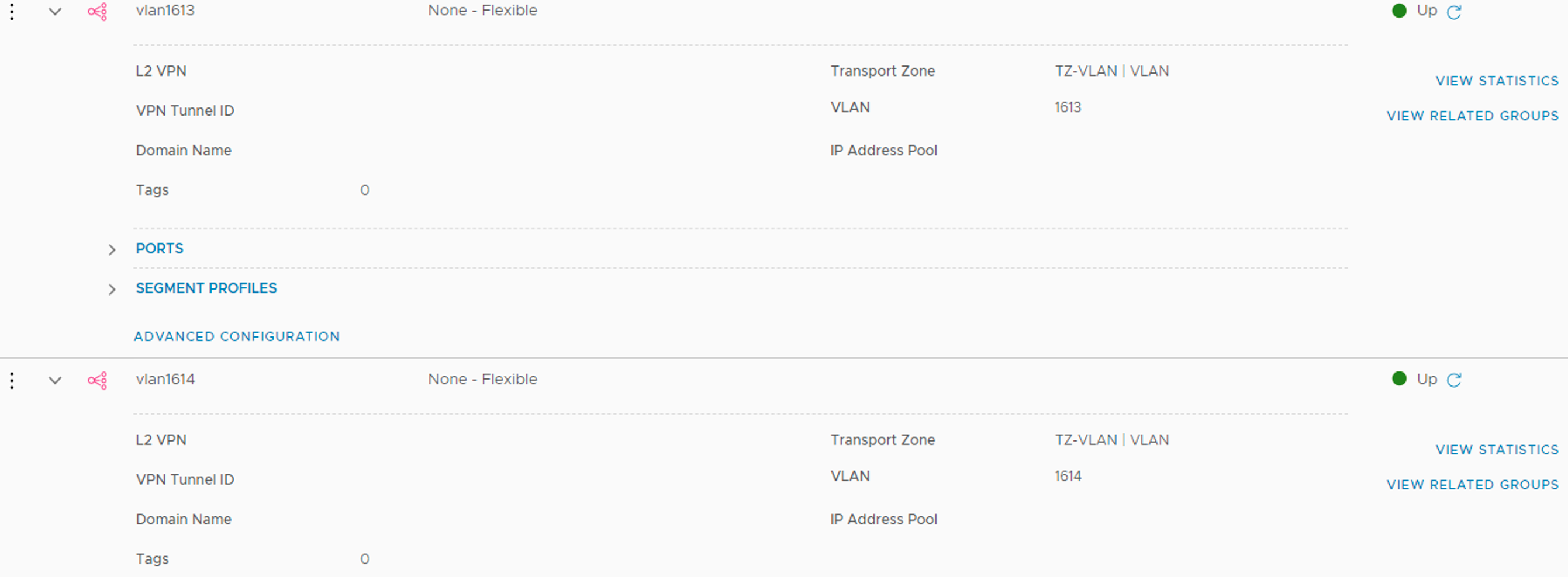
I create two new segments called vlan1613 and vlan1614 and configure them with VLAN ID 1613 and 1614 respectively:
Step 3 – Create a new NSX-T uplink profile
The way the Edge VMs connect to the physical network is different with the 2.5 Edge VM design. I need to configure a new uplink profile that contains the required configuration.
Uplink profiles are managed under System > Fabric > Profiles > Uplink Profiles:
The new uplink profile called EdgeVM-Uplink-Profile contains three teaming configurations.
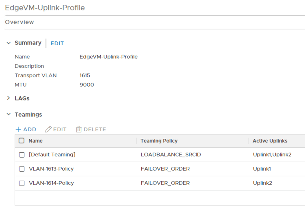
The [Default Teaming] is load balancing traffic between Uplink1 and Uplink2 and facilitates the multi-TEP capability of the 2.5 Edge VM design. The two other teaming configurations, VLAN-1613-Policy and VLAN-1614-Policy, are used for the point-to-point routing adjacencies.
Step 4 – Deploy new Edge VMs
As far as I know there is no easy way to reconfigure an N-VDS setup on existing edge transport nodes. I simply deploy two new Edge VMs that eventually will replace the existing Edge VMs:
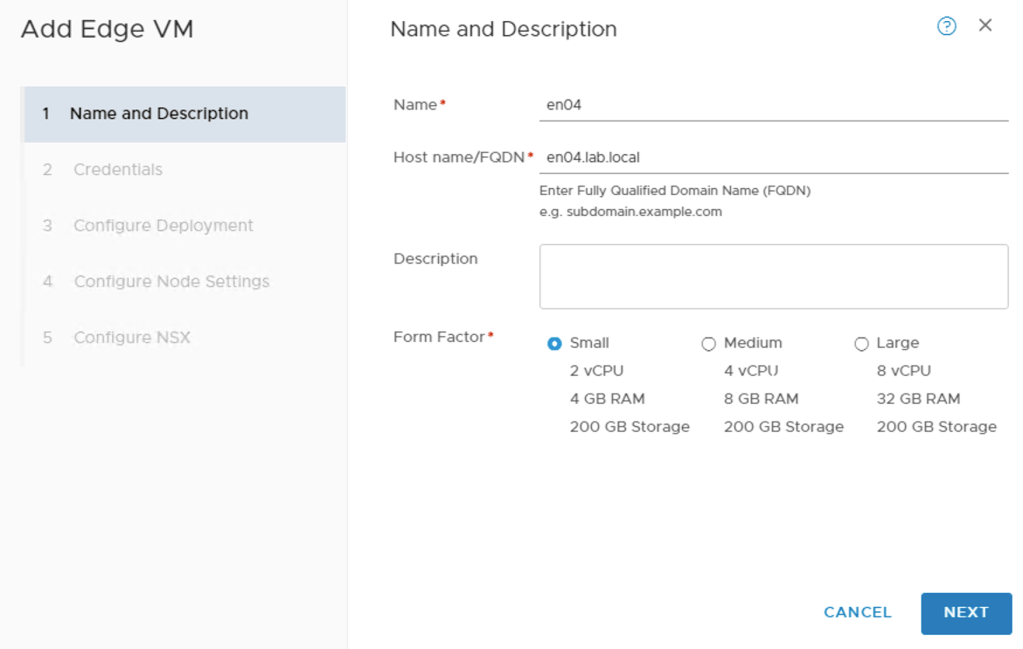
It’s at the Configure NSX step I configure the Edge VM according to the version 2.5 Edge VM design. So what does that look like? Something like this:
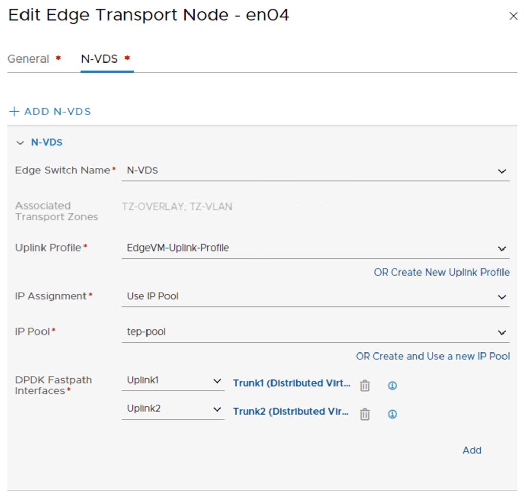
A single N-VDS that is associated with both an overlay and a VLAN transport zone. The EdgeVM-Uplink-Profile gives me two DPDK Fastpath interfaces that I assign to each their VDS trunk port group.
When deployment of the two new Edge VMs is finished I have the following situation under System > Fabric > Nodes > Edge Transport Nodes:
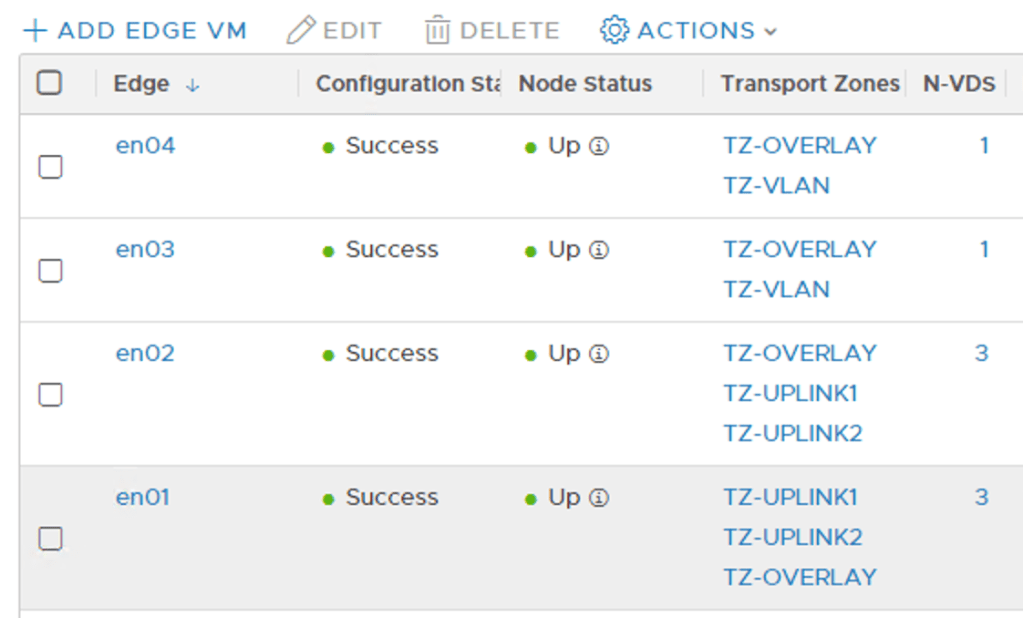
Edge nodes en03 and en04 are the new Edge transport nodes.
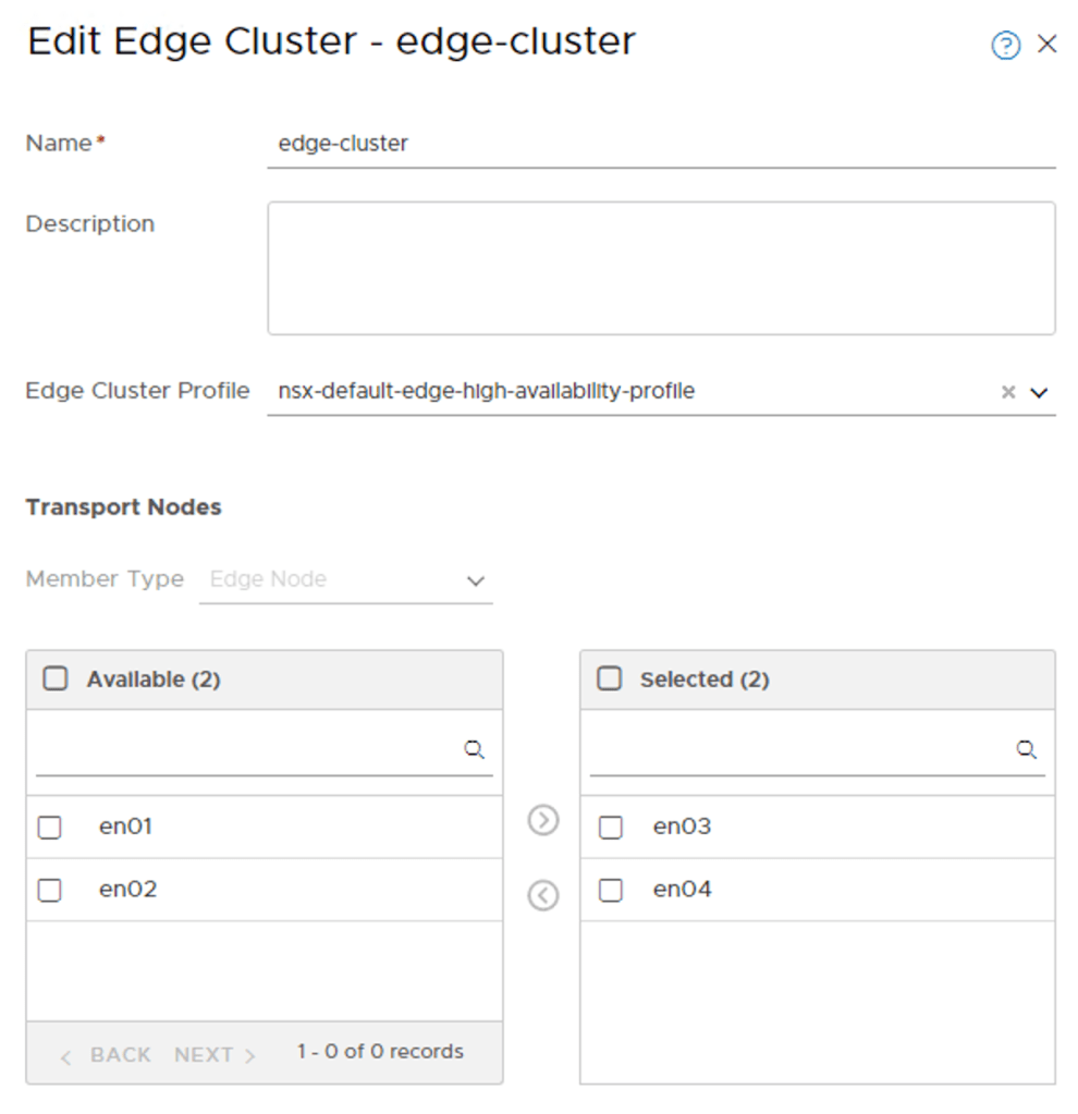
I add the new Edge transport nodes to the existing Edge cluster where they join en01 and en02:
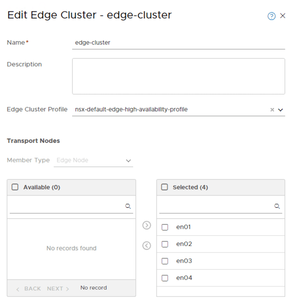
Step 5 – Transition
At this point en01 and en02 are the only Edge transport nodes with logical network configuration linked to them. While en03 and en04 are members of the same Edge cluster, they are not doing much in terms of data plane services.
A diagram of the L3 topology in my lab from an NSX Edge perspective:
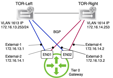
Transitioning to the new Edge transport nodes won’t and shouldn’t alter anything in the L3 topology above. Otherwise I would consider it a bad transition.
I’m ready to replace the current Edge transport nodes with the new ones. Unfortunately, the Replace Edge Cluster Member won’t work here as the nodes are having different configurations.
Instead I’m going to do a manual transition and in my simple lab environment that’s a pretty straight forward process. The only service hosted in the NSX Edge besides north-south routing is a DHCP server. So this should be easy.
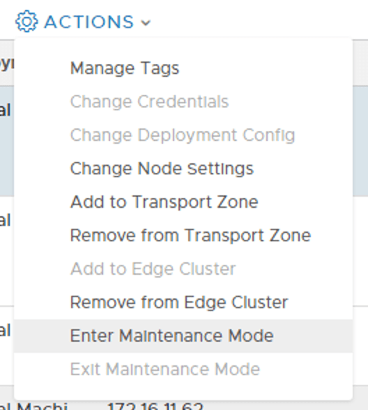
Starting by placing the en01 transport node in maintenance mode:
Now en01 is not involved in any data plane operations anymore. With that in mind I’m feeling comfortable going ahead with the next step which is the removal of the Tier 0 interfaces that are linked to en01.
My Tier 0 gateway has an active-standby HA mode which means it can’t have its configuration mapped to more than two Edge transport nodes at a time. By deleting the configuration linked to one Edge transport node I’m making room for a new Edge transport node. One at time.
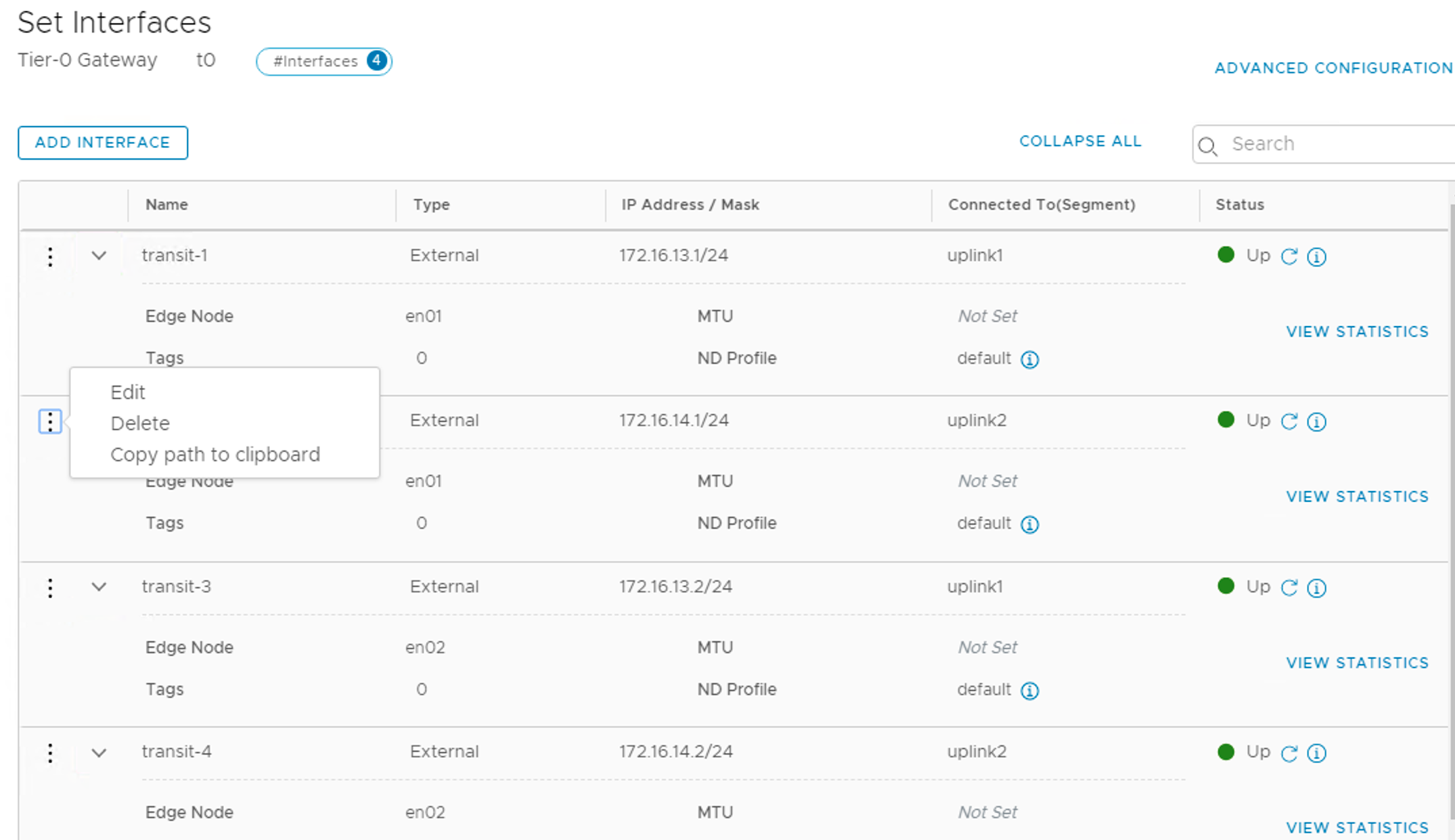
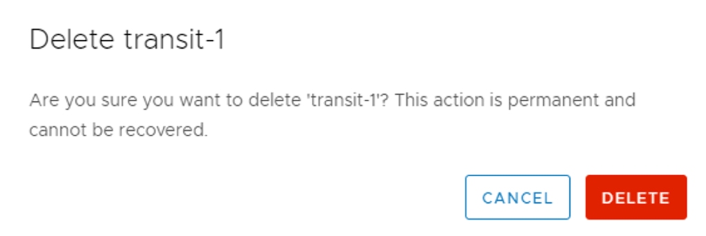
Deleting the interfaces will break the Tier 0 gateway’s en01 connection with the TORs, but this is acceptable as en01 has been placed in maintenance mode and the data plane won’t experience any disruptions.
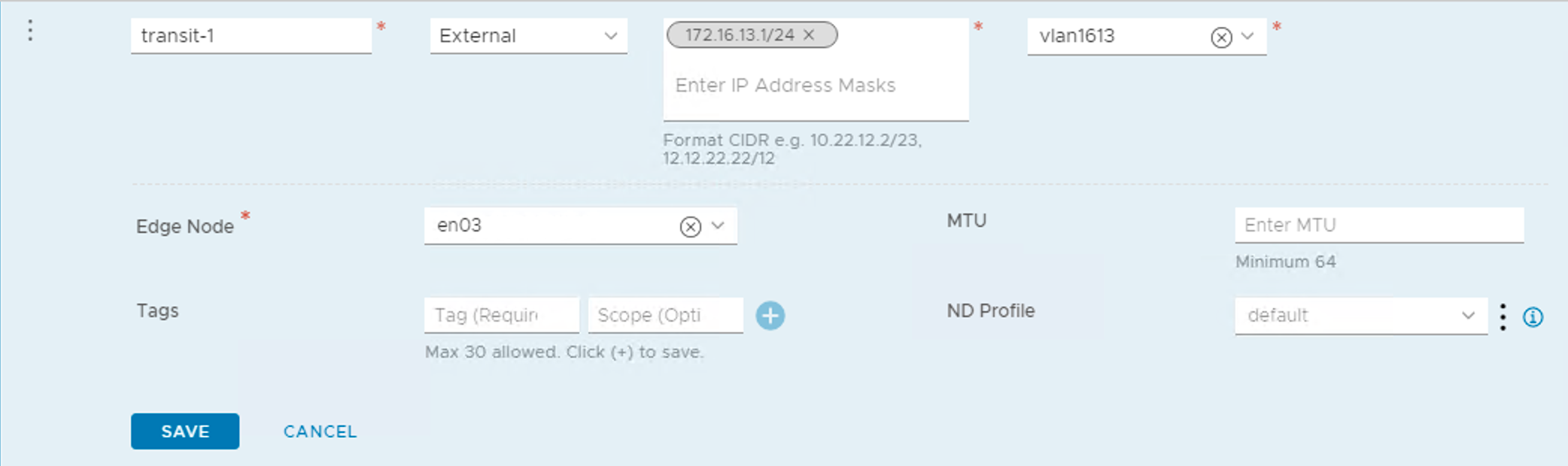
Once the two interfaces linked to en01 have been removed we can add them again with the same name and the same IP configuration as before, but this time I link them to en03 and select the newly created transit segments:
Once done with deleting and adding interfaces there’s a kind of hybrid situation where two Edge transport nodes (en02 and en03) each with a different deployment mode are serving the same Tier 0 gateway:
And it works!
Now I repeat the same process to replace en02 with en04:
- Place en02 in maintenance mode (en03 takes over its duties).
- Delete Tier 0 interfaces linked to en02.
- Add Tier 0 interfaces, link them to en04 and select the new segment
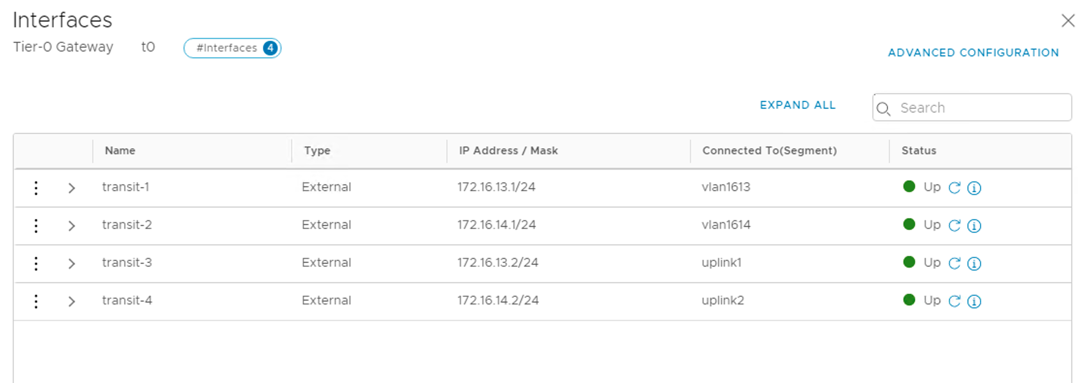
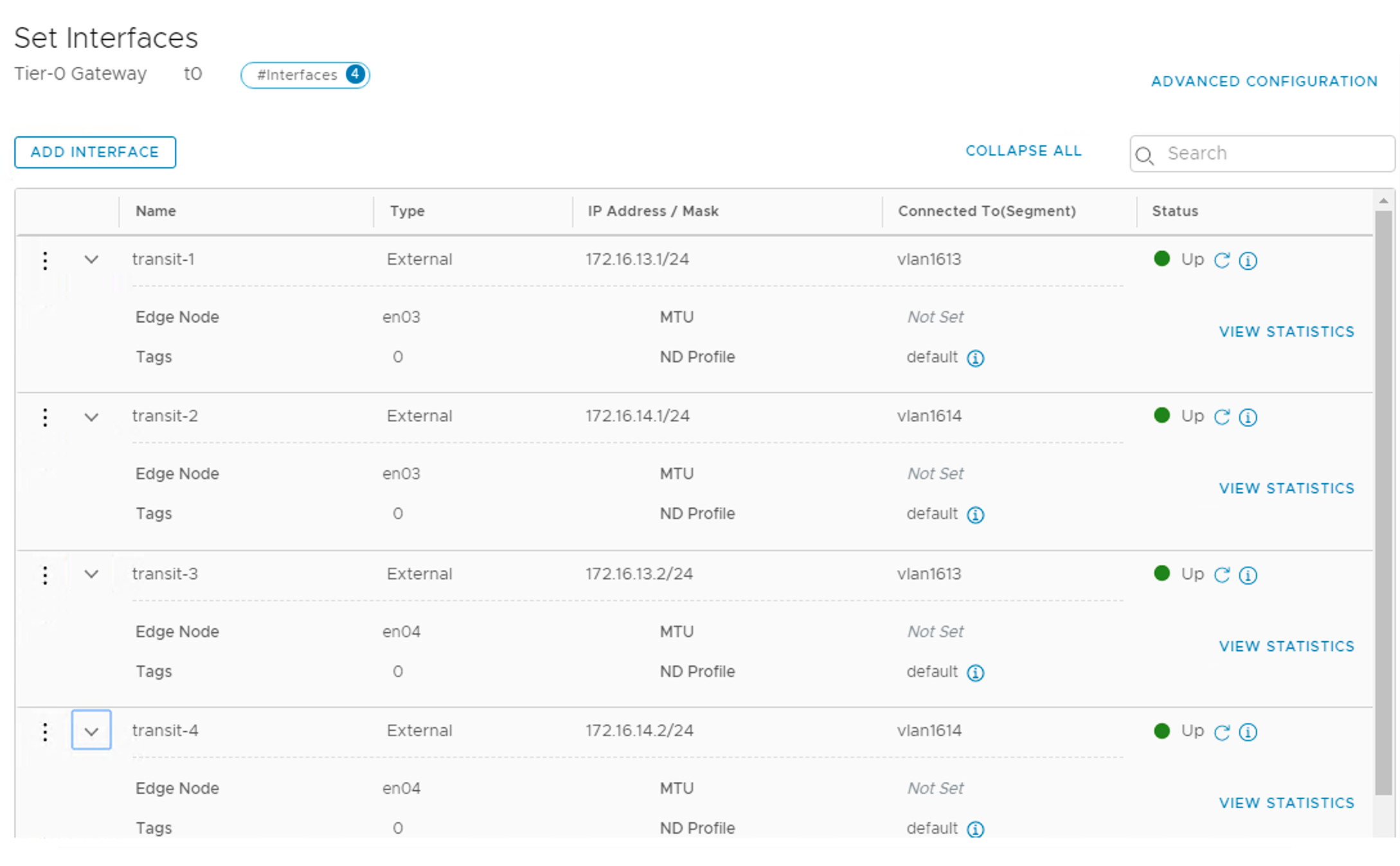
The final result is four Tier 0 gateway interfaces with the same name and IP as before, but linked to the new Edge transport nodes:
Just the DHCP service left which is pretty easy.
I have to re-configure the DHCP service so that it uses the new Edge transport nodes. This is done under Advanced Networking & Security > Networking > DHCP > Server Profiles
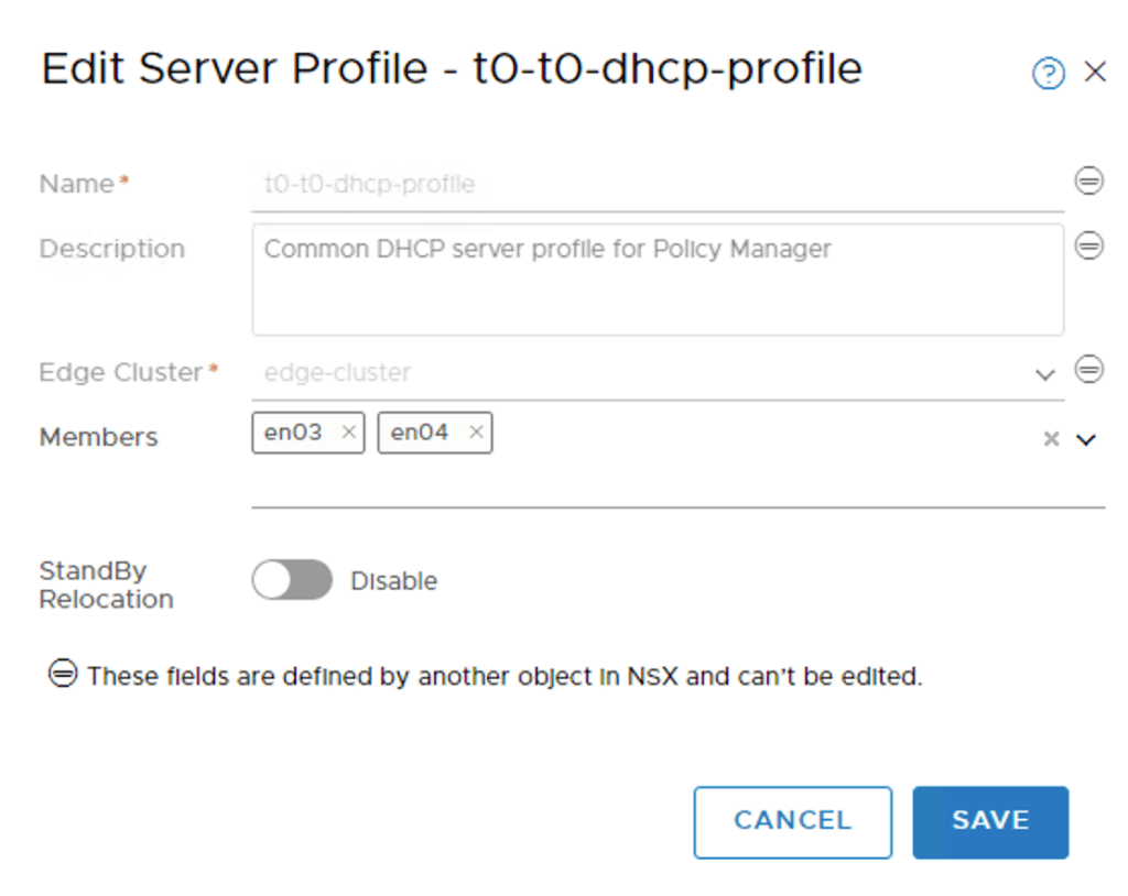
I edit the profile so that it only contains en03 and en04 as its members.
Step 6 – Clean up
After verifying that everything is working as it should the time has come to say goodbye to the old Edge transport nodes.
I first remove en01 and en02 from the Edge Cluster:
And then simply delete them from the fabric:

I can also delete the PG-OVERLAY, PG-UPLINK1, and PG-UPLINK2 port groups in vSphere as they are no longer needed.
This leaves the environment with the new en03 and en04 Edge transport nodes and the new NSX-T 2.5 recommended Edge VM design!
Summary
A summarization of the steps I took to go from a “three N-VDS Edge VM” design to a “single N-VDS Edge VM” design:
- Create trunking port groups in vSphere.
- Create new transit segments configured with VLAN ID.
- Create new uplink profile for the Edge transport node
- Deploy two new Edge VMs and configure them with the “single N-VDS” design.
- Replace the existing Edge transport nodes by doing a manual transition.
- Verify and clean up.
Quite an operation but certainly doable. It might or might not be worth the effort. It comes down to wether the advantages that this new Edge VM design offers are important enough to you.
Keep in mind that placing Edge transport nodes in maintenance mode as I did in this article will trigger a fail-over between the nodes (with active-standby mode) which in turn causes short data plane disruptions. That’s not an issue in a lab, but something to consider in a production environment. For a Tier 0 gateway with an active-active HA mode and ECMP enabled this would be less of an issue.

Leave a comment