Welcome back! We’re in the process of building an NSX-T Edge – FRRouting environment.
In part 1 we prepared the FRR routers by doing he following:
- Installed two Debian Linux servers
- Installed VLAN support
- Enabled packet forwarding
- Configured network interfaces
- Installed and configured VRRP
- Installed FRRouting
In this second part we will first deploy the NSX-T Edge components and then set up BGP routing. There’s a lot to do so let’s get started!
Target topology
As a refresher here is the big picture once more:
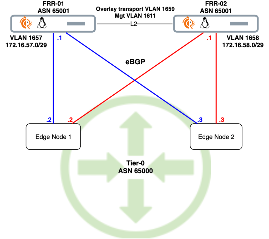
We’ll use this diagram as our blueprint. Scroll back up here any time you wonder what the heck it is we’re doing down there.
Deploy NSX-T Edge
Let’s begin by getting the NSX-T Edge on par with the FRR routers.
Create NSX-T segments
The FRR routers, frr-01 and frr-02, were configured with local “peering” VLANs 1657 and 1658 respectively. Corresponding VLAN-backed segments are needed for L2 adjacency with the FRR routers.
Creating the “vlan-1658” segment:
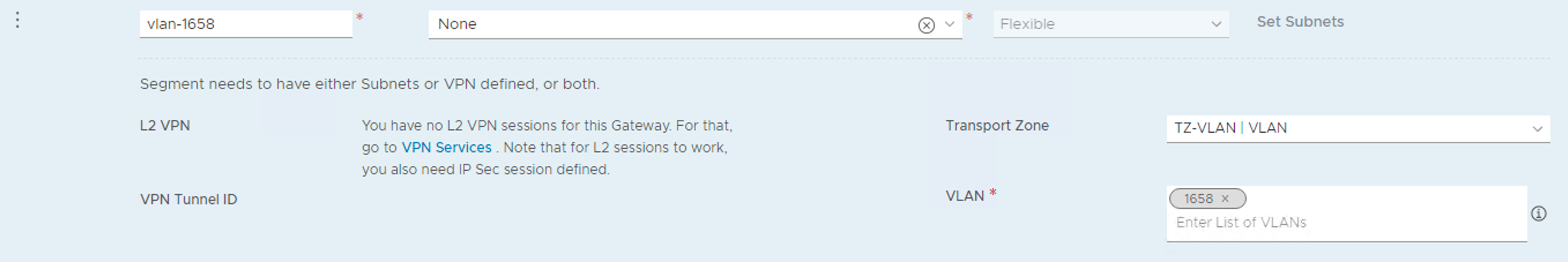
Both segments in place:

Uplink profile
Create an uplink profile for the edge transport nodes containing settings for teamings, transport VLAN, and MTU:
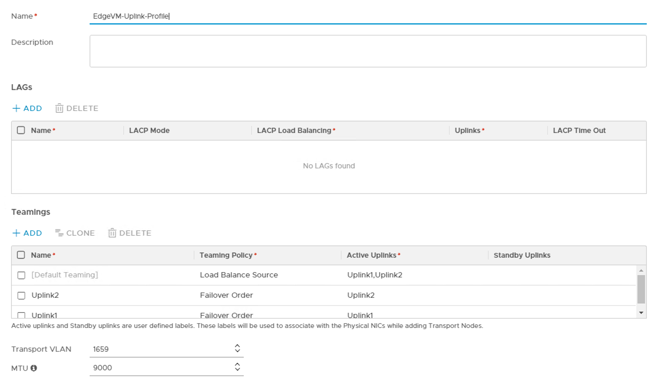
The transport VLAN has id 1659 and MTU size is 9000.
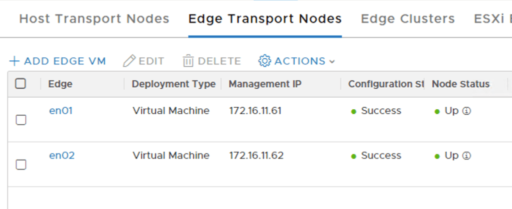
Deploy Edge VMs
Instead of walking through the Edge node deployment, the table below summarizes the settings I used during the deployment. Have a look at the Single N-VDS per Edge VM article for a detailed Edge node deployment walkthrough.
| Setting | Edge Node 1 | Edge Node 2 |
|---|---|---|
| Name | en01 | en02 |
| FQDN | en01.lab.local | en02.lab.local |
| Form Factor | Small | Small |
| Mgmt IP | 172.16.11.61/24 | 172.16.11.62/24 |
| Mgmt Interface | PG-MGMT (VDS) | PG-MGMT (VDS) |
| Default Gateway | 172.16.11.1 | 172.16.11.1 |
| Transport Zone | TZ-VLAN, TZ-OVERLAY | TZ-VLAN, TZ-OVERLAY |
| Static IP List | 172.16.59.71, 172.16.59.81 | 172.16.59.72, 172.16.59.82 |
| Gateway | 172.16.59.1 | 172.16.59.1 |
| Mask | 255.255.255.0 | 255.255.255.0 |
| DPDK Interdace | Uplink1 > Trunk1 (VDS) Uplink2 > Trunk2 (VDS) | Uplink1 > Trunk1 (VDS) Uplink2 > Trunk2 (VDS) |
The two Edge nodes are up and running:
We add both Edge nodes to an Edge cluster:

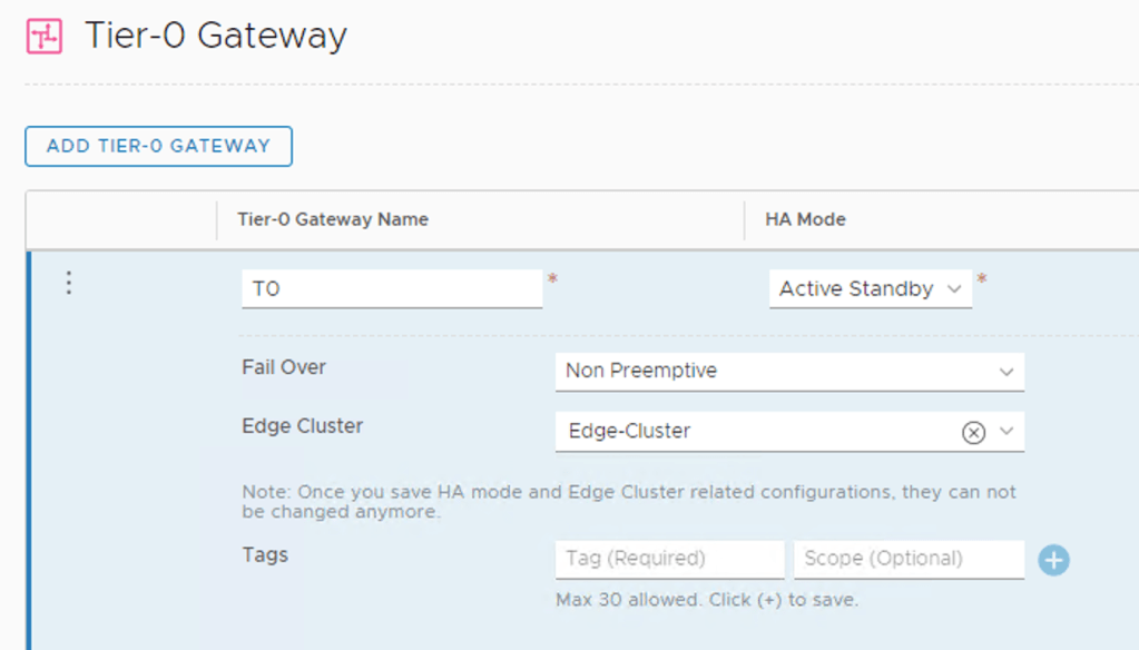
Create Tier-0 gateway
With the Edge nodes in place we can create a Tier-0 gateway. I’m configuring it with Active-Standby HA Mode:
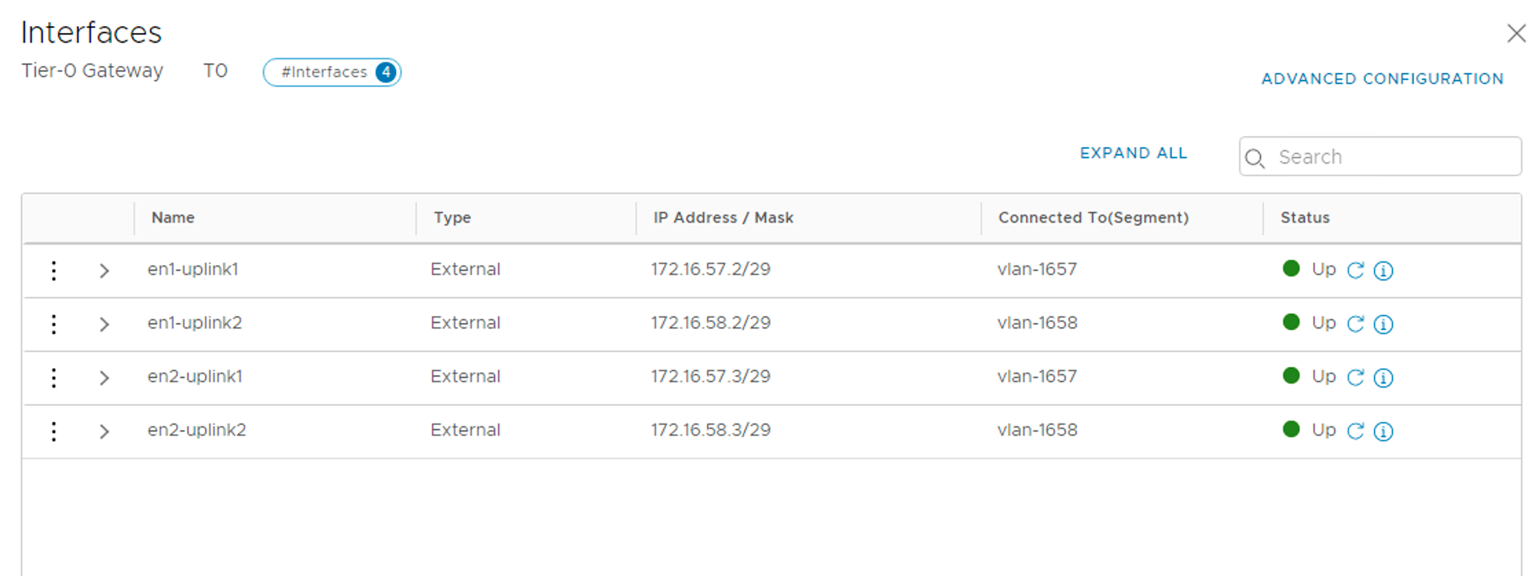
We add four external interfaces to the Tier-0:
| Name | IP address | Segment | Edge Node |
|---|---|---|---|
| en1-uplink1 | 172.16.57.2/29 | vlan-1657 | en1 |
| en1-uplink2 | 172.16.58.2/29 | vlan-1658 | en1 |
| en2-uplink1 | 172.16.57.3/29 | vlan-1657 | en2 |
| en2-uplink2 | 172.16.58.3/29 | vlan-1658 | en2 |
The four Tier-0 interfaces are in place:
Test connectivity
Now is a good time to verify the L2 adjacency between the FRR routers and the Tier-0 interfaces.
A ping from frr-01 to the Tier-0 interfaces in VLAN 1657:

And a ping from frr-02 to the Tier-0 interfaces in VLAN 1658:
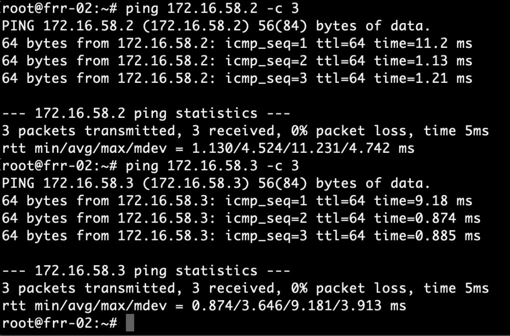
Successful pings. We’re good!
Configure BGP
Moving up an OSI layer, we continue with setting up BGP.
Tier-0 gateway
The Tier-0 is configured with the following BGP settings:
| Setting | Value |
|---|---|
| Local AS | 65000 |
| BGP | On |
| Graceful Restart | Disable |
| ECMP | On |
The settings in NSX Manager:

We add two BGP neighbors to the Tier-0: 172.16.57.1 (frr-01) and 172.16.58.1 (frr-02). Make sure to enable BFD for these neighbors too:

The neighbor status will be “Down” at this point which is expected as we didn’t configure BGP on the FRR routers yet.
For route re-distribution I choose to re-distribute from all the available sources into the BGP process:

FRR routers
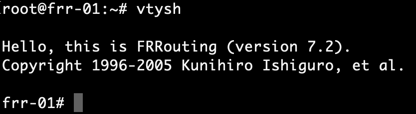
Configuration of BGP in FRRouting can be done by editing configuration files directly or through VTY shell which is FRRouting’s CLI frontend. We’ll use VTY shell today.
frr-01
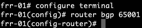
Run the vtysh command to start VTY shell:
After changing to the configuration mode with conf t, we enable the BGP process with:
router bgp 65001
Next, we configure the router ID and the BGP/BFD neighbors which are the Tier-0’s interfaces in VLAN 1657 on frr-01:
bgp router-id 172.16.57.1
neighbor 172.16.57.2 remote-as 65000
neighbor 172.16.57.2 bfd
neighbor 172.16.57.3 remote-as 65000
neighbor 172.16.57.3 bfd

We want frr-01 to advertise itself as the default gateway to its BGP neighbors which is accomplished with:
address-family ipv4 unicast
neighbor 172.16.57.2 default-originate
neighbor 172.16.57.3 default-originate

Run end followed by wr to save the configuration:

If all went well we should now see active BGP and BFD sessions between frr-01 and the Tier-0 interfaces in VLAN 1657. Let’s verify this with:
show bgp summary

BGP neighbor sessions are looking good. How about BFD?
show bfd peers

BFD sessions are up.
frr-02
We repeat the exact same configuration steps on frr-02. The configuration for frr-02 looks like this:
router bgp 65001
bgp router-id 172.16.58.1
neighbor 172.16.58.2 remote-as 65000
neighbor 172.16.58.2 bfd
neighbor 172.16.58.3 remote-as 65000
neighbor 172.16.58.3 bfd
!
address-family ipv4 unicast
neighbor 172.16.58.2 default-originate
neighbor 172.16.58.3 default-originate
exit-address-family
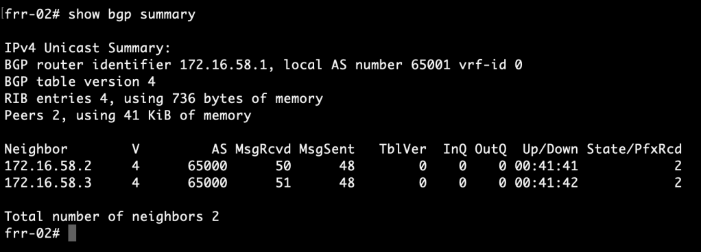
Let’s check the BGP/BFD status at frr-02:
show bgp summary
show bfd peers

BGP and BFD sessions are looking good.
Routing
After a lot of deploying and configuring it’s finally time to see if we can actually route any traffic.
FRR routing tables
We begin by having a look at the FRR routing tables. Run the following command in VTY shell on the FRR routers:
show ip route bgp
frr-01:

frr-02:
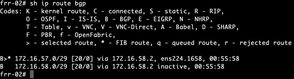
The FRR routers have learned about each other’s /29 subnets via the NSX-T Tier-0. More specifically, they were learned from neighbor 172.16.57.2 and 172.16.58.2. This tells us that the active Tier-0 SR is hosted on Edge node 1.
Is the standby Tier-0 SR completely out of the picture then? Let’s see:
show bgp detail

The standby Tier-0 SR on Edge node 2 also advertises routes for the same /29 subnets, but as you can see the ASN (65000) is added to the path three more times and packets won’t be routed over these longer paths.
Tier-0 routing table
Run the following command on the Edge node hosting the active Tier-0 SR:
get route bgp

Here we see two equal cost routes for 0.0.0.0/0, one to each FRR router. This tells us that “default-originate” did its job. Both routes also ended up in the FIB which means ECMP is working.
From overlay to physical
It’s now time for the ultimate test. We create an overlay segment, 192.168.10.0/24, connected to the Tier-0 gateway:

The BGP process on the Tier-0 advertises the 192.168.10.0/24 network to its neighbors. Let’s check if they ended up there:
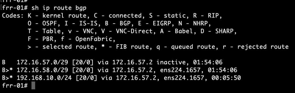
show ip route bgp
frr-01:
frr-02:

A route to the overlay network is indeed present in both of the FRR routers routing table.
Now we connect a VM to the overlay segment and run a traceroute from this VM to an IP address north of the FRR routers:
traceroute 10.2.129.10 -n -q 2

The VM on the overlay segment can reach the physical network. By doing two probes per hop we also see that the Tier-0 offers two paths to the destination: one via frr-01 (172.16.57.1) and one via frr-02 (172.16.58.1).
It’s a wrap
It’s been quite a project, but we got ourselves a working NSX-T Edge – FRRouting environment and it wasn’t that hard to set up, right?
This all started with me looking for a more enterprise like virtual top-of-rack solution for my NSX-T lab. Having these FRR routers north of the Tier-0 certainly feels like a big step towards that goal. Perhaps not fully showcased in these articles, but FRRouting’s feature set is pretty much on par with today’s data center leaf-spine switches. As a matter of fact it’s already being used there. Have a look at Cumulus Networks for example.
For more information about features and possibilities surrounding BGP have a look at the official NSX-T and FRRouting documentation. Most of all I recommend that you set this up yourself. Hopefully these two articles will help you get started with that.
Thanks for reading!

Leave a comment