Welcome to the final part of this series. We’ve come a long way.
After configuring North-South dynamic routing between the Tier-0 logical router and the “physical” (pfSense) router in part 5, it’s now time to add a Tier-1 logical router and some logical switches.
Tier-1 logical router
The purpose of Tier-1 routers is to facilitate for true multi-tenancy in the NSX platform. Tenants have their own T1 routers that connect to an administrator’s T0 router. Changes in the physical network do not necessarily affect tenants Tier-1 routers.
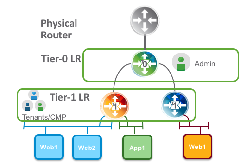
A Tier-1 logical router needs to be connected to a Tier-0 logical router to get the northbound physical router access. The connection between T1 and T0 is established over a special routerlink. This link is assigned a /31 subnet within the 100.64.0.0/10 reserved address space (RFC6598).
Deploying the Tier-1 logical router
In NSX Manager I navigate to Networking > Routing. Click on the “+ Add” button and choose “Tier-1 Router”:

A couple of things need to be specified here. I’m calling my T1 “tier-1-01” and pick the “tier-0-01” Tier-0 router I created in part 5. I also need to pick an Edge cluster, Failover Mode, Edge cluster members (Edge transport nodes), and a preferred member.

Clicking “Add” deploys the Tier-1 router.
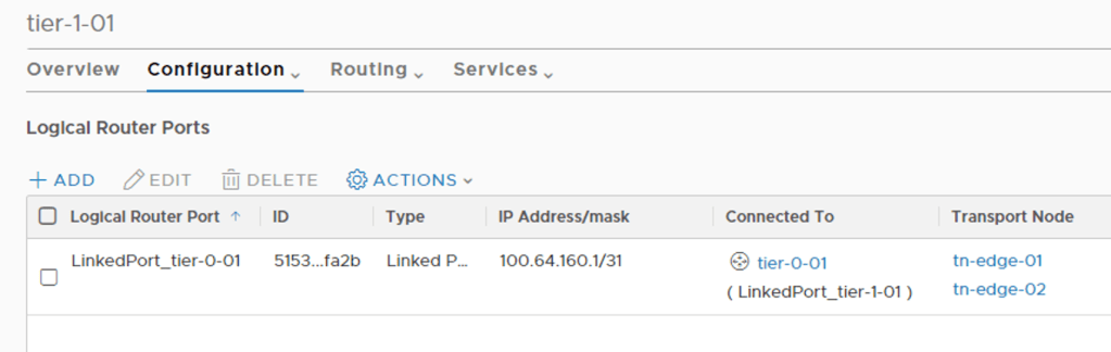
When clicking on the new Tier-1 router and having a look under Configuration > Router Ports I can see the special router port used for the routerlink to the Tier-0 router:
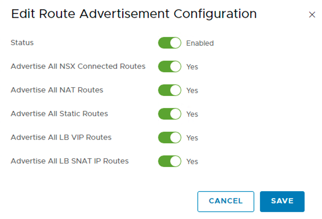
Logical networks created in NSX should be advertised to the Tier-0 and ultimately the physical router. For this to happen I need to configure Routing > Route Advertisement:

Here I choose to advertise everything that is available.
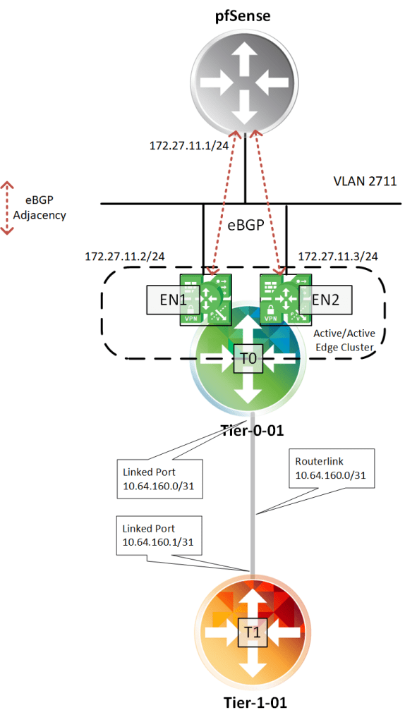
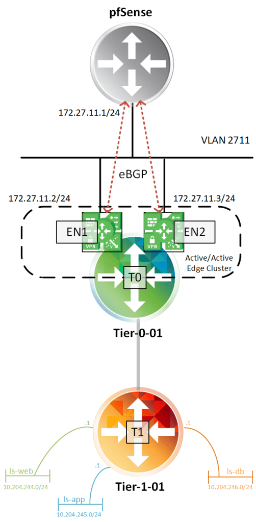
And that’s it for the basic configuration of my Tier-1 router. The logical router topology looks like this at this point:
Creating Tier-1 downlink ports
Downlink ports are Tier-1 router ports connecting to logical switches. They serve as a default gateways for the virtual machines that are in the same subnet.
I will create three downlink ports for now. I will deploy the classic three tiered network segments: web, app, and db.
On the Tier-1 router I once again navigate to Configuration > Router Ports. Adding the first router port called “rp-web”:
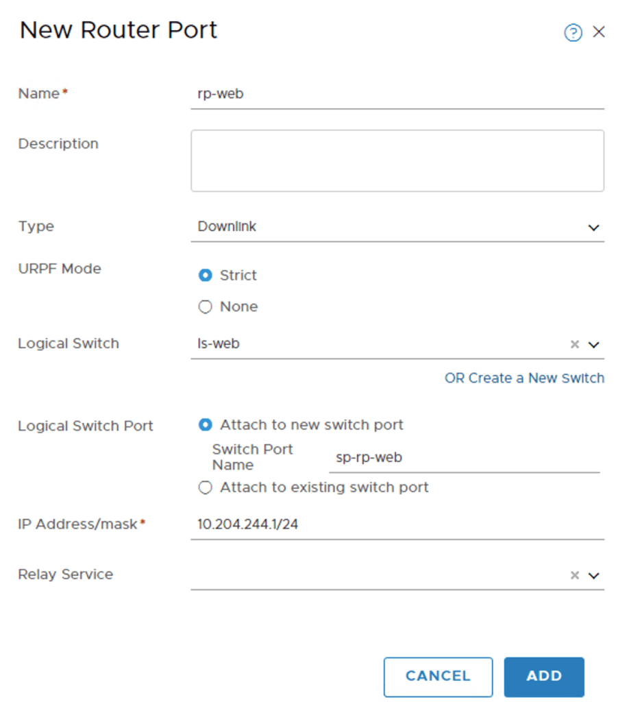
As you see I configured IP address 10.204.244.1/24 for this interface. It’s basically here I decide that the web IP subnet is 10.204.244.0/24.
You may have noticed that I also created a new logical switch called “ls-web” in the process. Its configured like this:

The logical is switch is part of the “overlay01” transport zone. No surprise here.
I repeat these steps to create the “rp-app”, and “rp-db” router ports and their associated logical switches
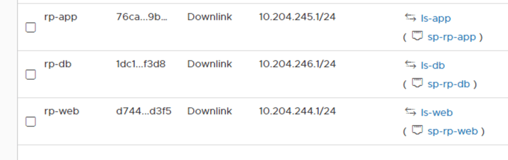

The topology with the logical switches attached to the Tier-1 router:
Looking on the Tier-1 router under Routing > Route Advertisement I can see that my three subnets are being advertised:

Verifying routing
Let’s see if the distributed router on the Tier-0 has these networks in its forwarding table. I log in to one of the Edge VMs CLI and change to the Tier-0 DR context:
get logical-router

The Tier-0 DR is living in VRF 6.
vrf 6
get forwarding

There are, among others, the three IP subnets associated with my newly created router ports. I see that the routerlink subnet 10.64.160.0/31 is used to get to the logical networks which seems to make sense.
Let’s also having a look at the Tier-0 SR context
vrf 3
get forwarding
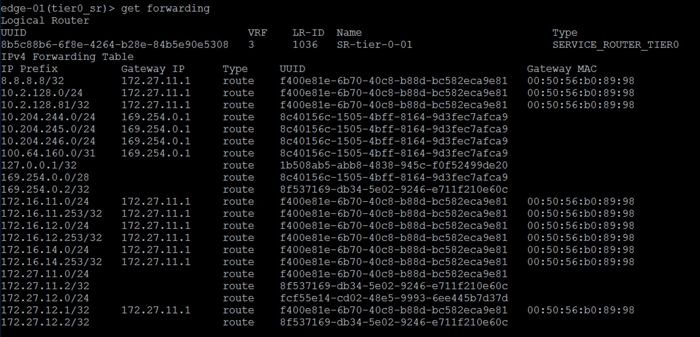
Beautiful! My new networks ended up all the way there too. As you can see the Tier-0 SR uses the intra tier transit link as the gateway to get to these networks. This is also as expected.
The million dollar question is: Are my new logical networks known on the physical network? Let’s check the forwarding table at my pfSense:
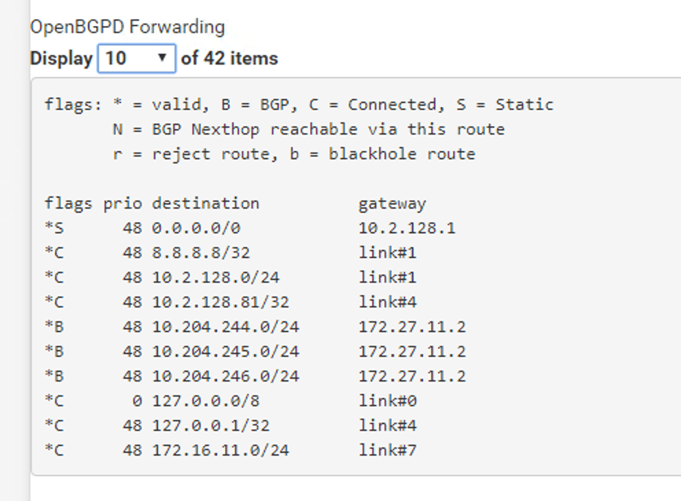
Absolutely. I’m seeing my three IP subnets in pfSense’s forwarding table. I can even ping the Tier-1 “rp-web” router port from the pfSense:

So this is where the NSX admin takes a step back and the VI admin comes in and starts deploying VMs on the new logical networks. 😉
Connecting a virtual machine
Speaking of which, how do I connect a VM to an NSX-T port group? It turns out to be really easy. NSX-T logical networks show up as N-VDS port groups in vCenter:

And therefore connecting a VM to an NSX-T logical network is done the usual way:

Conclusion
That’s it! This was a very basic NSX-T deployment in 6 parts. I hope you enjoyed it. There is much more to look at and configure in NSX-T, but the main platform is in place.
From here it will be about enabling features and possibly scaling out a bit. I expect to return to this lab environment in coming blog posts.
One thing that happened while I was writing the series was the NSX-T 2.4 release. There are a bunch of new features and improvements in version 2.4 and my next blog post might very well be about upgrading this environment to 2.4. Stay tuned!

Leave a reply to Angelo Cancel reply