
NSX-T 3.0 comes with brand new features for logical networking in multisite environments. With NSX-T Federation the platform effectively receives a location-aware management, control, and data plane and this gives us, the implementers and architects, some very interesting new options when designing and installing NSX-T 3.0 in a multisite scenario.
Although Federation affects all major components of the NSX-T platform, in today’s article I want to have a closer look at a relatively basic, yet very common and popular use case: setting up stretched logical networking.
It’s going to be quite an exercise so let’s get right to it!
The environment
In this greenfield scenario we’ve been given access to two new data centers:
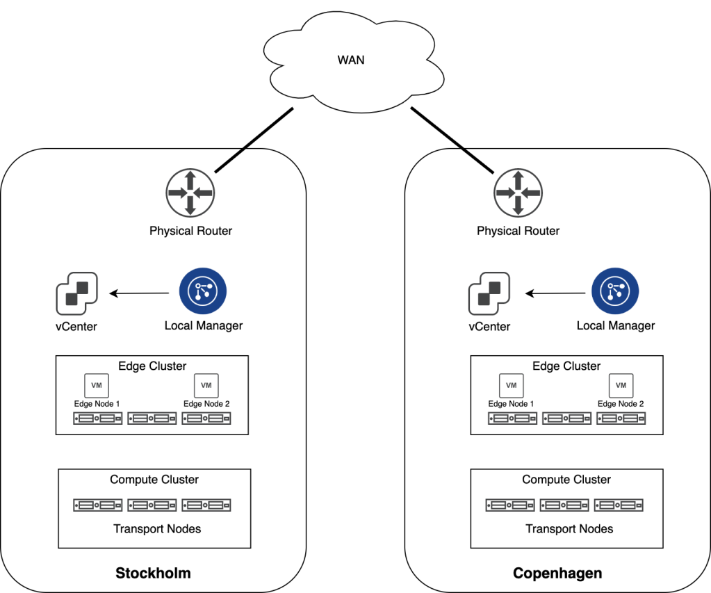
Both DCs are running vSphere 7 with a dedicated cluster for the customer’s workloads and another for the NSX-T Edge. Local Managers have been installed in each DC and ESXi hosts in the Compute Clusters have been configured as transport nodes. Edge Nodes have been deployed and are part of an NSX-T Edge Cluster. Transport zones for VLAN, overlay and Edge have been created, but apart from that no other logical networking has been configured.
The assignment
The customer wants us to set up a stretched logical network between the Stockholm and Copenhagen data centers so that workloads can connect to the same logical network regardless of their physical location. Local egress should be implemented so that northbound network traffic egresses via the nearest physical router.
The implementation
Time to get our hands dirty and find out what it takes to get this up and running.
Step 1 – Deploy Global Manager
NSX-T Global Manager is a new component in NSX-T 3.0 and required when setting up Federation. In Federation the Global Manager is the central point of administration pushing configuration to the relevant Local Managers.
A Global Manager is deployed from the same OVA that is used to deploy a Local Manager. We just select the NSX Global Manager role in the deployment wizard:

After installing the Global Manager in the Stockholm data center we need to activate it. This is done in the Global Manager UI under System > Configuration > Location Manager > Global Manager:

And we have an active Global Manager in the Stockholm DC:

Step 2 – Add locations
With the Global Manager alive and kicking we can start adding the Local Managers. This is done under System > Configuration > Location Manager > Locations:

Once the Local Managers for Stockholm and Copenhagen are added to the Global Manager we have this nice looking overview in the Global Manager UI:

Step 3 – Create IP pools for RTEP
We need an IP pool in each location that provides IP addresses to the RTEP interfaces on the Edge Nodes. In each Local Manager UI navigate to Networking > IP Management > IP Address Pools and add a new IP pool:
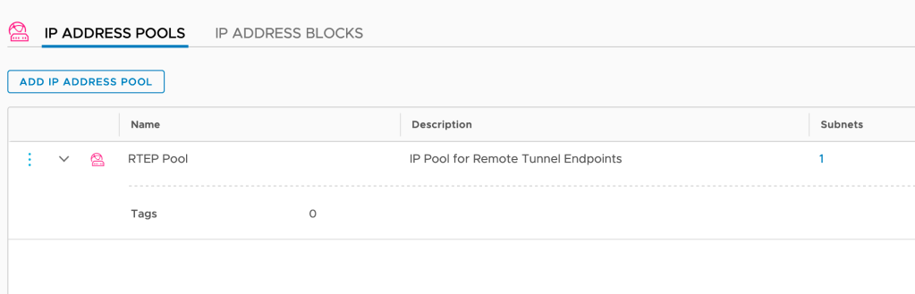
Note: With NSX-T Federation we need an additional VLAN per location for RTEP.
Step 4 – Configure Edge Nodes
The Edge Nodes need to be configured for stretched networking. This task is initiated from the Global Manager, but the actual configuration is done on each of the Local Managers.
From the Global Manager UI we navigate to System > Configuration > Location Manager > Locations:

For each of the locations we click Networking:

The existing NSX-T Edge Cluster is detected and Global Manager proposes we use it for inter-location communication. In this case that’s indeed what we want so let’s click the “Configure” button and find out what happens:

We’re directed to the Local Manager where I’m selecting both Edge Nodes and fill out the “Remote Tunnel Endpoint Configuration” form.

We repeat this process for the other location.
Step 5 – Create stretched Tier-0 Gateway
Now things are starting to get interesting. We’re about to deploy a stretched Tier-0 Gateway, but before we do we first need to create Tier-0 uplink segments for each location.
Segments
These are created from the Global Manager UI under Networking > Connectivity > Segments:

Note that these are VLAN-backed segments. Make sure that you pick the right location and corresponding VLAN ID when creating the uplink segments.
Tier-0 configuration
Now let’s get the stretched Tier-0 Gateway up and running. In the Global Manager UI navigate to Networking > Connectivity > Tier-0 Gateways and click the Add Tier-0 Gateway:
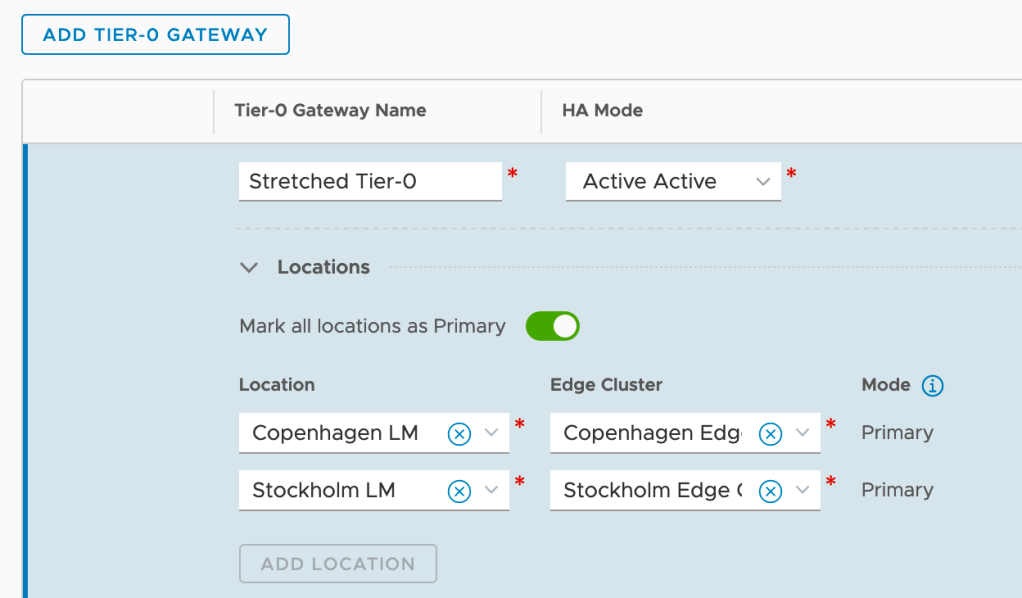
As you can see I’m configuring this Tier-0 with Active-Active HA Mode and also enable it to be primary at all locations. This means is that each site will utilize their local Tier-0 SR/DR components running on the local Edge Nodes. In other words we are configuring local egress. Without enabling “Mark all locations as Primary” we would configure central egress.
Tier-0 interfaces
The Tier-0 SR components at each site need connectivity with the physical network. This is achieved by creating Tier-0 external interfaces. In this scenario both Stockholm and Copenhagen will “contribute” with four Tier-0 external interfaces:

Adding these interfaces is a delicate job. Especially when working with a stretched Tier-0 Gateway you need to make sure that you pick the right location, configure the right IP address, and select the right uplink segment.
Tier-0 routing
A Tier-0 that ain’t routing ain’t a Tier-0 goes the saying. I’m going to start with configuring some default routes pointing to the physical network so that the workloads can find their way out of NSX-T:
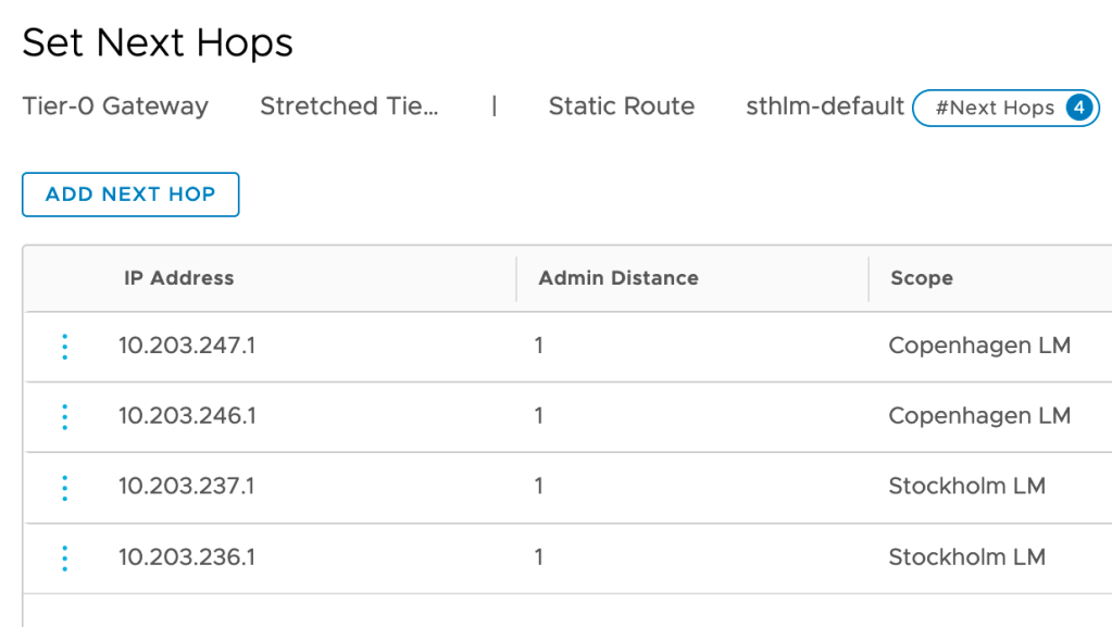
Note that static routes now have the “Scope” attribute which is instructing the Tier-0 to apply a static route only where it’s relevant.
Next, I’m setting up BGP routing between the stretched Tier-0 and each site’s physical routers/ToRs:
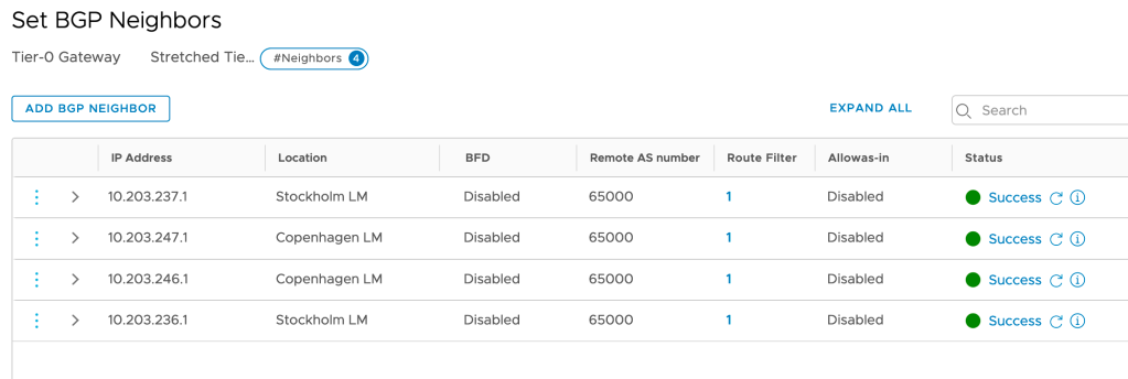
As you can see BGP neighbor entries are also tied to a location.
The last thing I’m setting up is route re-distribution which, again, is configured per location:

We now have a stretched Tier-0 instance up and running!
Step 6 – Create stretched Tier-1 Gateway
Creating a stretched Tier-1 Gateway is a straightforward process. From the Global Manager UI navigate to Networking > Connectivity > Tier-1 Gateways > Add Tier-1 Gateway:
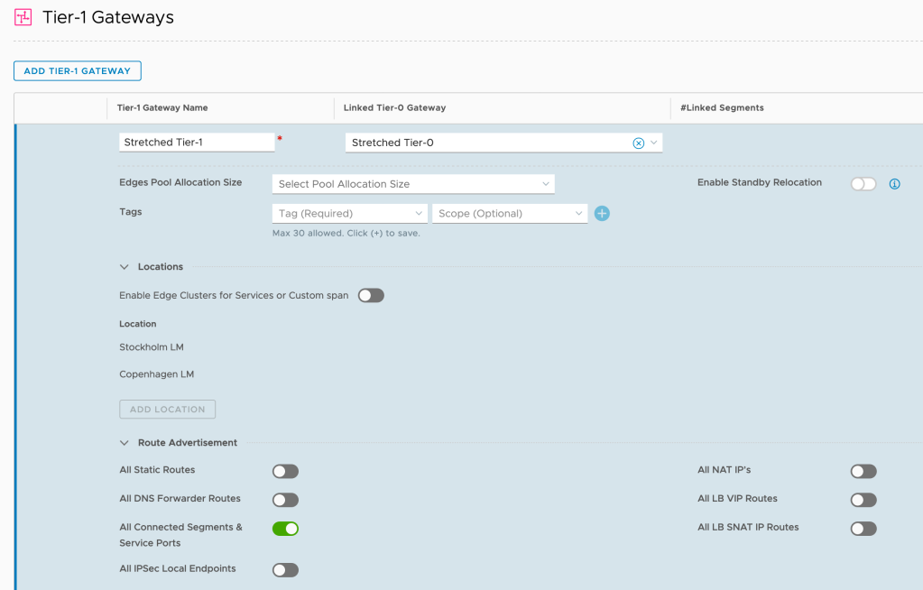
There’s not that much to explain here. The stretched Tier-1 is linked to the stretched Tier-0. I also enable route advertisement for all connected segments so that the Tier-0 and physical network will know how to get to them.
Step 7 – Created stretched overlay segment
Finally, here comes the stretched overlay segment. This is the moment we’ve all been waiting for. In the Global Manager UI navigate to Networking > Connectivity > Segments > Add Segment:

Again, a very straightforward process. I’m attaching the stretched overlay segment to the stretched Tier-1 which is linked to the stretched Tier-0.
Step 8 – Connect workloads
Now that we have a stretched logical network available in both Stockholm and Copenhagen, it’s time to connect a workload or two and see if all our hard work has actually been of any use.
In Stockholm’s vCenter I connect a VM called “Web Server Stockholm” (IP address 10.10.10.100/24) to the “Stretched Segment” NSX port group:

In Copenhagen I’m doing the same thing for a VM called “Web Server Copenhagen” (IP address 10.10.10.200/24):

We now have two workloads connected to the stretched logical network. Each of them located at a different site.
Review
Let’s have a brief look at what we’ve been building. Starting with the Network Topology map produced by the Local Managers in Stockholm and Copenhagen:

The following diagram shows things from an inter-site routing perspective:

The logical router components are primary in each DC which, as mentioned, enables local egress. Keep in mind that local egress comes with its own set of challenges (not controlled by NSX-T) and is not always desired.
Verify
Verification is best done from the workloads running in the different data centers. Let’s start with the VM in Stockholm pinging the VM in Copenhagen:

That seems to be working fine. Now let’s have the Stockholm VM ping its default gateway (the Tier-1):

Very nice and a pretty low latency as well. Let’s now run a traceroute from the VM in Stockholm to a physical server:

The path from the Stockholm VM to the physical server is via the Tier-1 (10.10.10.1) over the router-link to the Tier-0 (100.64.176.0) then to the physical router in Stockholm (10.203.236.1) and from there to the destination (10.203.0.5).
Let’s do the same traceroute exercise from the VM in Copenhagen:

So here we can see that the path goes from the Tier-1 (10.10.10.1) over the router-link to the Tier-0 (100.64.208.0) then to the physical router in Copenhagen (10.203.247.1) and from there to the destination (10.203.0.5).
So these simple traceroutes tell us that connectivity between the Tier-0 and the physical network is operational and that local egress is doing its thing with traffic is egressing through each site’s local physical router.
Summary
It’s been a battle, but it was worth it, right?
NSX-T Federation is an extremely welcome addition to the platform. Already in this early release it’s making things so much easier and more beautiful from a lot of perspectives. Designing and implementing multisite NSX-T just became fun again and undoubtedly many customers will start looking at implementing Federation in their multisite environments.
Thanks for reading.
References and resources:

This is very good article in Stretched Networking through NSX-T Global manager.
LikeLike
Great info and explanation!!!
LikeLike
Do you need enterprise license for this implementation?
LikeLike
Hi Frank,
NSX-T Federation requires the Enterprise Plus edition.
Click to access vmware-nsx-datasheet.pdf
LikeLike
Good Evening. I noticed in Step 4, that the field/value for “Inter-Site MTU” is 1500 bytes. This is not matching the multi-site deployment requirements in Vmware Doc “https://docs.vmware.com/en/VMware-NSX-T-Data-Center/3.0/administration/GUID-5D7E3D43-6497-4273-99C1-77613C36AD75.html”. Is it being used by the Overlay communication/transport across sites?
LikeLike
Hi Luis,
That’s a requirement for traditional NSX-T multisite. This article is highlighting NSX-T Federation which consists of some additional components. For RTEP MTU the recommendation is “as large as your physical network connections supports”
Cheers
LikeLike